Mechanical components and light from outside the intended field of view can cause contamination of the image,how to analyse its impact on an opto mechanical system, this article will share the insight about it.
Rays hitting the lens barrel and the housing holding the optical components are scattered and can reach the detectors. The following images show an opto-mechanical system, including mechanical components designed by CAD software. You can download the sample file from the end of this article.
Lens spacers are in between the lenses, pressure/retaining rings hold the lenses, and a lens mount covers the entire the opto-mechanical system. The following example shows how to identify, analyse and solve the ambient light impact on the opto mechanical system.

The mechanical components in this opto mechanical system include CAD parts and annulus that is the stop aperture of the optical system. In this example, we’ll apply identical reflection and scattering characteristics for all mechanical components.
- Reflectance: 5 %
- Specular reflectance: 0.5 %
- Scattering reflectance: 4.5 %
- Scatter Model: Lambertian

We add a Source Ellipse at the entrance aperture of the opto-mechanical system to simulate a source of ambient stray light. The position and the diameter of the source are the same as the physical entrance aperture. The Lambertian light source is one of candidate models because the ambient stray light source is required to emit rays to omnidirectionally to simulated light which can enter the opto mechanical system from outside the field of view.

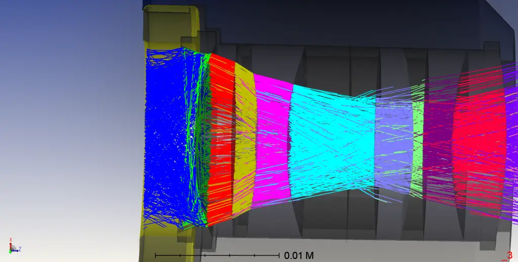
Below is the display layout of the system. The rays displayed are rays passing through the optical system or scattered by the mechanical components, then reaching the detector.

Next, let’s execute the ray trace to get the ZRD file. And then close all the sources except of Source Ellipse we recently added, to simulate the ambient light. When the ray trace is complete, and then let’s conduct Path Analysis.
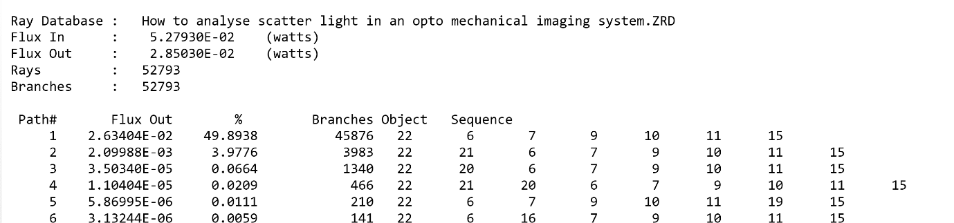
Path 1 is the designed optical path which propagates through the lenses in sequence and hits the detector without scattering from mechanical components.
In paths 2 and 3, the rays are scattered by opto mechanical components (object 20 and 21) marked by red rectangles. These are the pressure/retaining rings. These paths have the only one scatter event.
The following figure shows the rays of path 3.

The output from the Path Analysis tool allows us to identify the most significant ambient stray light paths in the opto system. We have an insight about which parts of the opto mechanical system (in this case objects 20 and 21) need modifications to their geometry and surface characteristics to reduce the effect of the ambient scattered light from the mechanical components.
The design file used in this particle is attached, please download it here. How to analyse scatter light in an opto mechanical imaging system
Reference Source:
- https://www.zemax.com/
- Zemax Optical Design Program User’s Guide, Zemax Development Corporation
- https://en.wikipedia.org/wiki/Main_Page
