Stray light means light that does not enter the system through a designed path, before reaching the image plane and degrading the intended image, how to observe it in the design stage, this article will share a bit about it.
It is often essential, prior to physical prototyping, to investigate the effects of stray light on the performance. Light from such sources can reach the image plane via scattering from the mechanical or optical components for the system. Alternatively, light from a source inside the field of view can undergo multiple secondary reflections at lens surfaces before focused on the image surface.
In this example, we will use 210 degree wide angle imaging system as example to demo how to observe stray light. You could download the design file at the end of this article.

First we need to lock down the design using Design lockdown tool, this will adjust the system settings so that the lens meets the real conditions and the analysis results are more correct. Before converting to Non-Sequential Mode, let’s export the key rays in the Sequential Mode, which consists of the chief ray and a series of marginal rays. This allows us to directly examine the critical rayset in the Non-Sequential Mode, otherwise the rayset could only be calculated in the Sequential Mode.
Noted about chief ray and marginal ray: the chief ray is defined to be the ray that travels from a specific field point, through the center of the entrance pupil, and on to the image surface. The marginal ray is the ray that travels from the center of the object, to the edge of the entrance pupil, and on to the image surface.
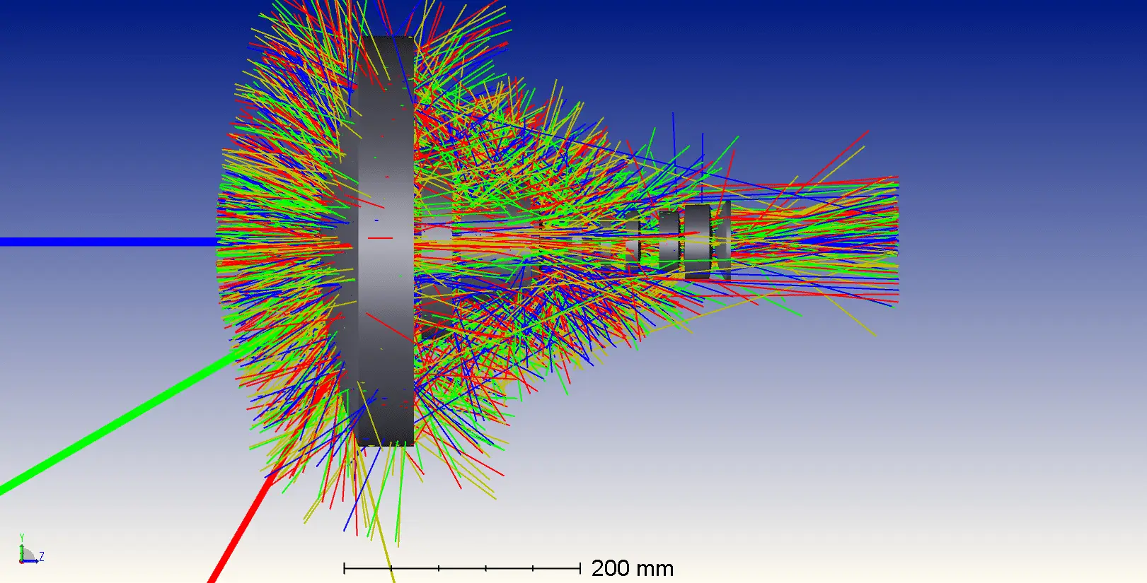
The system has been changed to pure Non-Sequential Mode. All the lenses have been converted from surfaces to object. We can also see that several light sources and detectors have been included to represent the field points and image locations from the Sequential system. This system is the same as the original Sequential Mode except that it is built in Non-Sequential Mode.

Check Split NSC Rays. We can observe partial reflection partial transmission and multiple reflections of the rays on each lens surfaces. This is what we can’t see in the Sequential Mode.
Check the status of the critical rayset
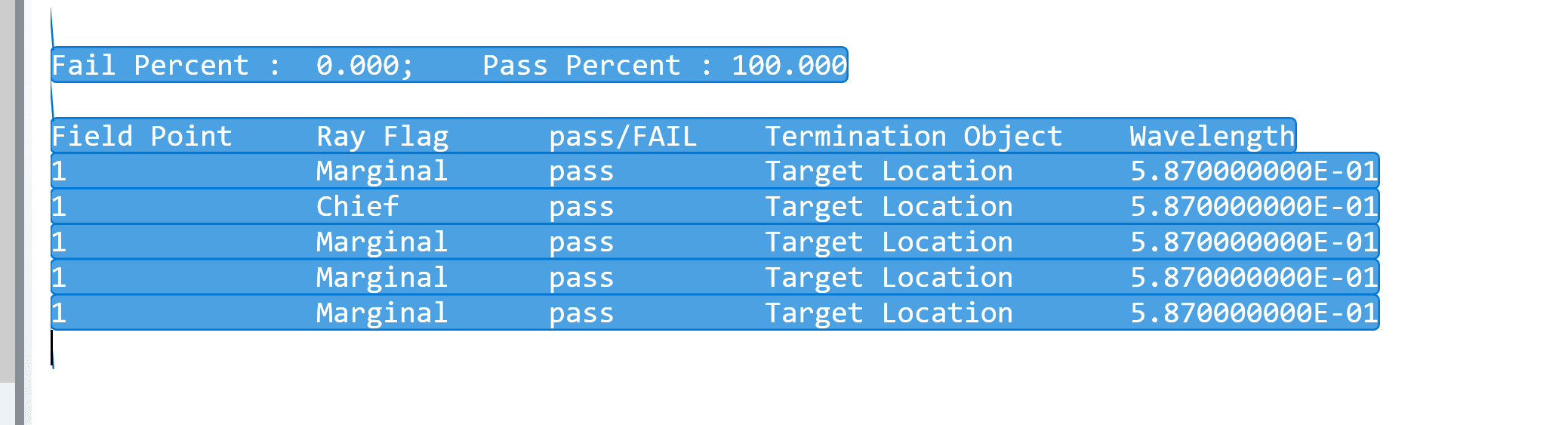
You will see that the chief and marginal rays of each field can pass normally through the Non-Sequential system. When mechanical components are designed and added to the system, as imported the CAD files, it will be necessary to use the tool again to ensure that they do not block the critical rayset.
Next, let’s trace the ray by setting the Maximum Intersections Per Rays and Maximum Segments Per Rays to the maximum number (4000 and 2000000 respectively). In the stray light analysis, sometimes the light we want to analyze will reflect and scatter many times. If the settings for the maximum number of segments or intersections are insufficient, it may not be possible to analyze all conditions.
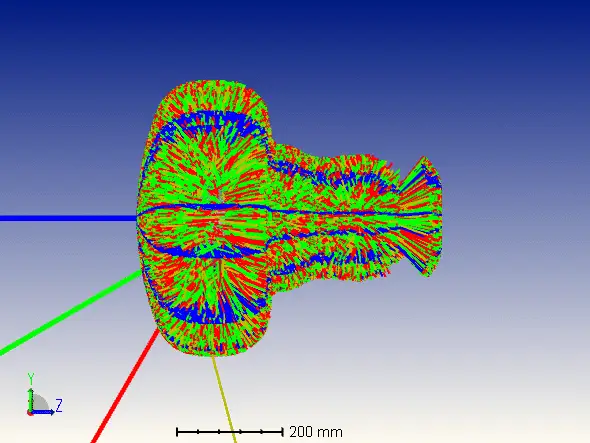
We have reduced the number of Analysis Rays to 5000. We can now look at the preliminary ray trace results.
You can see the stray light, which are sky-blue points like snowflakes shown as below picture, in this system due to multiple reflections.
The design file used in this particle is attached, please download it here.How to analyse the stray light in an imaging system-PROD-NONSEQ
Reference Source:
- https://www.zemax.com/
- Zemax Optical Design Program User’s Guide, Zemax Development Corporation
- https://en.wikipedia.org/wiki/Main_Page
