The most important purpose for the stray light analysis is to find the “source” caused the ghost Image and try to resolve it. This article will share how to do it.
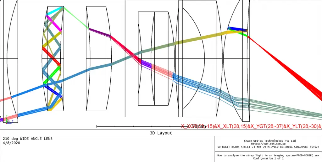
Now let’s find out the causes of the ghost image lighting and explore ways to reduce it. The figure below is the example of 210 degree imaging system, and you could download it at the end of this article. It shows the unintended reflected light (ghost light) on the image surface.


Next, we will use a technique to separate the light with stronger energy that is incident on the image plane (detector) from the ghost light. This technique is achieved by setting the Minimum Relative Ray Intensity. The value entered represents the ratio of the light relative to the light source. The default is 1.000E-6, which means that the ray will always be traced until the value is less than 1.000E-6 times of the initial energy. This is a simple way to filter out the weak ghost rays and remain only strong ghost image rays. Enter a value of 0.0005, which will cause to stop tracing rays when their energy is less than 0.0005 times the original energy.

We will introduce Path Analysis feature, which is a better way to identify the strongest stay light path.
After these initial steps to eliminate ghost image light, we find that there is still unexplained ghost image light on the detector, mainly in an point at the bottom-center of the image. Suppose we want to know from where the ghost image light is coming. What should we do?

We will use a combination of four instructions to filter only those rays incident one the specific area of the detector highlighted above. X_XGT(28,-15)&X_XLT(28,15)&X_YGT(28,-37)&X_YLT(28,-30).

From the Layout, you can see all the paths to the specified area on the image plane. But there is a problem. There are too many possible paths. Based on experience, we know that it is impossible for all paths to be strong. In these paths, it is likely that one or two of them are the main contributors of ghost image light. We should focus on the paths that contribute the most energy.
Let’s narrow down the source of ghost image by path analysis.
This tool groups rays from a ZRD file according to the path the rays took through the system. Rays that took the same path, in terms of the order different objects were interacted with, are summed so the total flux in each path can be determined.

After analysis, you can see that almost the first ghost image energy (0.03%) is concentrated on the path of 1. Let’s go back to Layout and see which path it is. Displaying the first path found in the advanced path analysis tool into the Filter String is easy. Add a &_1 to the end of the original Filter String, and you can see the following picture.

Let’s zoom in to see the details:

Aha! The analysis found that this path generated by the reflection on the side of the lens. In fact, this will not happen once we add a good AR Coating. We finally find the source of the “ghost Image”!
The design file used in this particle is attached, please download it here.How to identify the source of “Ghost Image” lighting
Reference Source:
- https://www.zemax.com/
- Zemax Optical Design Program User’s Guide, Zemax Development Corporation
- https://en.wikipedia.org/wiki/Main_Page
