Ambient light from mechanical components and external sources can significantly impact the image quality of an optical system. Stray light contamination, caused by rays hitting the lens barrel, housing, or other mechanical components, can scatter and reach the detectors, introducing noise and reducing system performance.
This article explains how to analyze the impact of stray light on an opto-mechanical system using ray tracing and path analysis.

Understanding the Stray Light Contamination Process
In an opto-mechanical system, components such as lens spacers, pressure/retaining rings, and lens mounts can scatter light into the optical path. These scattered rays are unwanted and may impact the image, especially when the system is exposed to ambient light or stray radiation from outside the intended field of view.
In the following analysis, we will use CAD models of the opto-mechanical system to identify and simulate the effects of ambient light contamination.
Mechanical Components and Stray Light Simulation
To simulate the effect of stray light contamination, we assign the following optical properties to the mechanical components:
- Reflectance: 5% (includes both specular and scattering components)
- Specular Reflectance: 0.5% (specular reflection on smooth surfaces)
- Scattering Reflectance: 4.5% (scattered light due to surface roughness)
- Scatter Model: Lambertian (diffuse scattering model)

We place a source ellipse at the entrance aperture of the system to represent ambient stray light. The Lambertian light source is a suitable model because it simulates omnidirectional scattering, allowing light to enter the optical system from outside the field of view.

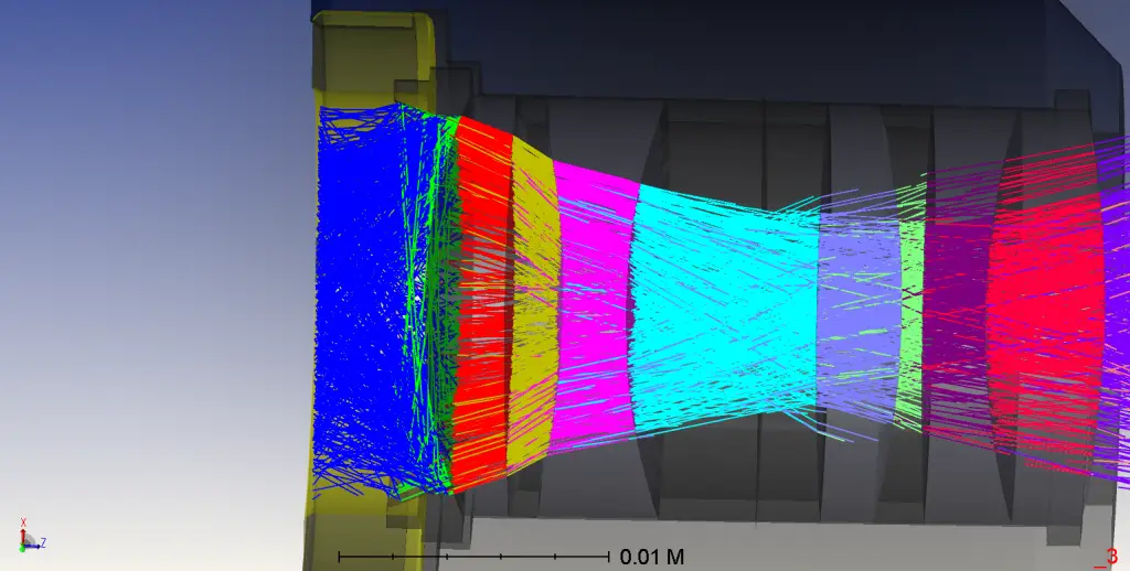
Below is the layout of the system. The rays displayed are rays passing through the optical system or scattered by the mechanical components, then reaching the detector.

Ray Tracing and Path Analysis
Ray Trace Execution:
First, we execute the ray trace with all sources enabled, including the ambient light source. This generates a ZRD file, which provides information about the rays propagating through the system.Simulation of Ambient Light:
Next, we close all other light sources except the source ellipse to focus only on the impact of ambient light. This simulates the stray light entering the system from external sources.Path Analysis:
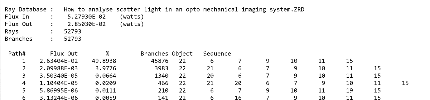
The Path Analysis tool in Zemax helps track the rays’ paths through the system, identifying both direct optical paths (Path 1) and scattered light paths (Paths 2 and 3). The scattered light originates from mechanical components (objects 20 and 21, in this case, the retaining rings).
Results and Interpretation
- Path 1: Rays traveling along the designed optical path pass through the lenses in sequence, reaching the detector without any scattering from mechanical components.
- Path 2 and 3: These rays scatter off the pressure/retaining rings and reach the detector. These paths are marked by a single scatter event.
The Path Analysis tool helps identify the most significant stray light paths that influence the image quality. By reviewing the analysis, we can identify which mechanical components (such as the retaining rings) need modifications in their geometry or surface characteristics to minimize stray light contamination.

Optimizing the System Design
By understanding the paths through which stray light travels, optical designers can adjust the system to mitigate its impact. This may include:
- Modifying the surface finish of mechanical components to reduce scattering
- Altering the geometry of the parts causing significant stray light contamination
- Adding baffles or light shields to prevent stray light from reaching the detector
Conclusion
Analyzing stray light contamination in opto-mechanical systems is crucial for improving the performance of optical systems. By using tools like ray tracing and path analysis in Zemax, you can identify sources of ambient light and make targeted design changes to reduce its impact.
References
- https://www.zemax.com/
- The design file used in this article is attached. How to analyse scatter light in an opto mechanical imaging system