The physical optics model is generally more accurate at predicting the detailed amplitude and phase structure of the beam away from focus than conventional ray tracing, here we share a few examples, hope it will help you.
Geometrical optics is the modeling of optical systems by tracing rays. Rays are imaginary lines which represent normals to the surfaces of constant phase, called the wavefront. Either rays or wavefronts can be used to represent a beam. However, rays and wavefronts are propagated differently. Rays propagate along straight lines without interfering with one another, wavefronts propagate while coherently interfering with themselves. The ray method is fast, flexible, and extremely useful for modeling almost any optical system. However, rays are not well suited to modeling certain important effects, primarily diffraction. When using POP, the wavefront is modeled using an array of points. Each point in the array stores complex amplitude information about the beam. The array is user-definable in terms of its dimension, sampling and aspect ratio.
Geometrical optics and the single step approximation work quite well for the majority of traditional optical designs, where the beam is not near focus anywhere except the final image. However, the model breaks down for several important cases:
- When the beam comes to an intermediate focus, especially near optics that truncate the beam (rays by themselves do not predict the correct distribution near focus).
- When the diffraction effects far from focus are of interest (rays remain uniform in amplitude and phase, wavefronts develop amplitude and phase structure).
- When the propagation length is long and the beam is nearly collimated (collimated rays will remain collimated over any distance, real beams diffract and spread).
Physical optics is the modeling of optical systems by propagating wavefronts. The beam is represented by an array of discretely sampled points, analogous to the discrete sampling using rays for a geometric optics analysis. The entire array is then propagated through the free space between optical surfaces. At each optical surface, a transfer function is computed which transfers the beam from one side of the optical surface to the other. The physical optics model allows very detailed study of arbitrary coherent optical beams, including:
- Gaussian or higher order multi-mode laser beams of any form (beams are user definable).
- Beams may be propagated along any arbitrary field position (skew beams).
- Amplitude, phase, and intensity may be computed at any surface in the optical system.
- Effects of finite lens apertures, including spatial filtering, may be modeled.
- Accurate computation of propagation through any optical component.
Physical Optics Propagation is a very powerful tool, which allows you to analyze the effects of coherence and diffraction at every optical surface in the system.
Talbot Imaging
Talbot imaging refers to the property of a beam forming an image of itself as it propagates. The image reveals itself in both phase and amplitude modulations as the beam propagates.

The example as below shows a user defined aperture on surface 1 that consists of 20 rectangular slits, like a grating. A propagation of 20 mm reveals the phase reversed Talbot image of the grating. An additional 20.0 mm shows the restored image of the grating.


The POP is setting as below:


The image is not perfect because of the finite extent of the grating. Note the region near the center of the grating has a well formed image.
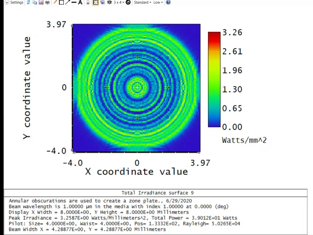
This example illustrates the focusing power of an aperture consisting of concentric rings.

Since Zemax does not have a multiple-zoned circular aperture, the zone plate was created by placing one annular obscuration on each of several surfaces; all located at the same plane. The option to “Use Rays To Propagate To Next Surface” is used to speed the computation through all the aperture surfaces.

The spacing of the rings is selected to block light from every other Fresnel zone, so that at a distance of 200.0 mm the light diffracted from all the zones interferes constructively.

The constructive interference creates a bright focused spot on axis; an effect not predicted by ray tracing.

This example also illustrates the intensity of the beam at several planes between the Fresnel zone plate and focus; note the concentric ripples caused by interference from the edges of the zone plate.
The example “Basic Propagation” illustrates the case of a beam propagating through free space. The beam is a Gaussian defined to have a waist of 0.1 at surface 1. The wavelength is chosen to be π micrometers so that the Rayleigh range is 10.0 mm.

At a distance of 1 Rayleigh range, the beam expands in size by root (2), and the peak irradiance drops to 0.5. At a distance of 2 Rayleigh ranges, the peak irradiance drops to 0.2, and at 3 Rayleigh ranges the irradiance decreases to 0.1.


- Note that beam may be virtually propagated backward using the normal Zemax sign convention of a negative thickness.
- Note the phase of the beam along the axis has the correct Gouy shift.
Reference Source:
- https://www.zemax.com/
- Zemax Optical Design Program User’s Guide, Zemax Development Corporation
- https://en.wikipedia.org/wiki/Main_Page
