Shape Optics just have a new task to use He-He Laser source to design a focusing system, it is to simulate and design a lens system to focus the beam at its minimum size @ 30mm. In this example, we will show when we could we use “ray based simulation”, and what is the condition we could use the ray to represent the Laser source.

About our He-Ne Laser source
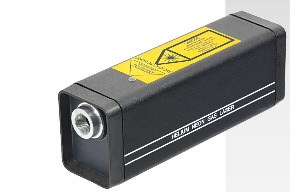
A helium-neon Laser source, typically called a HeNe laser, is a small gas Laser source with many industrial and scientific uses. The primary wavelength they are used at is 632.8 nm, in the red portion of the visible spectrum. The gain medium of the laser is a mixture of helium and neon gases in a 5:1 to 20:1 ratio that is contained at low pressure in a sealed glass tube. The excitation source for these lasers is a high-voltage electrical discharge through an anode and cathode at each end of the glass tube. The optical cavity of the Laser source consists of a flat, high-reflecting mirror at one end of the laser tube and an output coupler mirror with approximately 1% transmission at the other end. In most interferometric applications, the most relevant parameter is the coherence length, which is determined by the axial modes that are furthest apart. For a red HeNe Laser source, the coherence length is approximately 30 cm.

Our Laser source specs is as below:

Design task:
Design a lens system to focusing the Laser source beam with minimum size @ 30mm from the Laser source output.
Knowing the wavelength and the far field divergence angle, using the equitation list in What Is the Key Points in Laser source Optics Propagation , the beam waist is calculated to be 0.1184 mm, with a Rayleigh range of 69.7 mm. the distance of waist to measurement point is: 122.77mm. We will focus the beam using a singlet lens as example.
Please note: Geometrical optics is the modeling of optical systems by tracing rays. Rays are imaginary lines which represent normals to the surfaces of constant phase, or the wavefront. For a paraxial Gaussian beam, within the Rayleigh range, z < zR, the beam size changes very slowly.

In this case, beam can be modeled as collimated ray bundle. When far outside the Rayleigh range, z >> zR, beam size changes linearly with propagation distance, so beam can be modeled as a point source.

As shown, when using rays to model Gaussian beam, we need to know if the propagation is within the Rayleigh range or outside Rayleigh range. This can help us decide if we should use a point source or a collimated ray bundle to model the beam. In this case, we know the beam waist location is inside of the Laser source housing. And we have calculated beam waist 0.118 mm and Rayleigh range 69.7mm, we can manually calculate the beam propagation distance z from its waist, around 122.78 mm, when the beam hits the measurement location. Since this propagation distance is not much larger than the beam Rayleigh range, z>>zR, we cannot model the beam using a point source. However, the propagation distance is also outside of Rayleigh range, we also cannot use the parallel beam.
We tentatively use ray-based method to design the system and validate our judgment above.
The design setting and layout as below.

Find the optimize beam size and location
Above we used pure ray-based approach to optimize the singlet lens so that the beam size is the smallest at 30 mm away from the Laser source output. As we know the Laser source beam diffracts as it propagates through the space, which cannot be modeled by ray-based approach. While we know that the focused spot size reported by the ray based calculation is not accurate in this case.
Here, we’ll only look at the Paraxial Gaussian Beam results using 1D Universal Plot. This plot shows the computed paraxial Gaussian beam size as a function of the image plane location.

In the plot, you can see the smallest Gaussian beam size occurs at a back focal distance around 26 mm, which turns out to be not very close to our current back focal distance 30mm. This suggests the image location found by ray-based optimization is not yielding the smallest geometrical spot size also does not result in the smallest Gaussian beam size computed by the Paraxial Gaussian Beam tool. In other words in this system the smallest spot location found by ray-based approach doesn’t agree well with the location of the smallest Gaussian beam size.
In this case, Paraxial Gaussian beam analysis and physical optics propagation are the best method to represent the Laser source beam, and should be the best method to simulate the system. We will share it in the future.
The design file used in this particle is attached, please download it here.How to apply and simulate a He-Ne 632 Laser application
Reference Source:
- https://www.zemax.com/
- Zemax Optical Design Program User’s Guide, Zemax Development Corporation
- https://en.wikipedia.org/wiki/Main_Page
