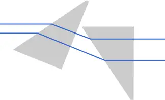
Anamorphic prism pairs are an essential optical tool used for variable magnification along one axis, collimating elliptical beams (e.g., laser diodes), and converting elliptical beams into circular beams. They work by magnifying or contracting the input beam in one axis, providing effective beam shaping for a variety of optical systems.
Principle of Beam Shaping with Anamorphic Prism Pairs
The operation of anamorphic prism pairs is based on changes in the beam radius rather than focusing effects (i.e., changes in wavefront curvature). Unlike lenses or mirrors, these prisms rely on refraction at flat interfaces. When a beam interacts with the surface of a prism, the angle of incidence (and thus the beam path) is modified due to Snell’s law, creating an alteration in the beam radius.
In an ideal setup, one interface may use normal incidence and another may use Brewster’s angle, which minimizes reflection losses. This setup ensures maximum throughput (around 95%) when prisms are properly oriented with anti-reflection coatings.
Anamorphic Prism Pair Dependency on Angle
When a parallel beam passes through a prism pair, the beam’s radius in the direction of the plane changes, effectively expanding the beam. However, the beam radius in the perpendicular direction remains unchanged. This makes the prism pair useful for changing beam dimensions in one direction without altering the beam direction.
The overall magnification of the system depends on the refractive index of the prism material. For example, if the prisms have a refractive index of 1.5, the overall magnification would be the square of the refractive index (or the inverse, depending on orientation).

Practical Aspects of Using Anamorphic Prisms
Anamorphic prisms can be purchased as single items or mounted prism pairs, which are easier to integrate into optical systems. Some setups feature rotatable mounts for precise realignment.
However, it’s important to note that the chromatic dispersion of the prism material can cause wavelength-dependent deflection angles, limiting the operational wavelength range. This issue can be mitigated by using prisms made from materials with suitable refractive indices for the desired magnification.
While anamorphic prisms can’t correct astigmatism (a distortion of the beam), they offer advantages over cylindrical lenses in beam shaping. For instance, cylindrical lenses can introduce astigmatism, but anamorphic prisms do not. They also offer greater tolerance in terms of transverse positioning.
Comparing Beam Shaping Methods
Some experiments suggest that spatial filtering improves beam circularity but at the cost of transmitted power. The cylindrical lens pair achieves a balanced circularization of the beam with minimal astigmatism but with a reduction in power. In contrast, the beam output from the anamorphic prism pair exhibits better M2 values and less wavefront error than cylindrical lenses, although it results in lower transmitted power.


Reference

