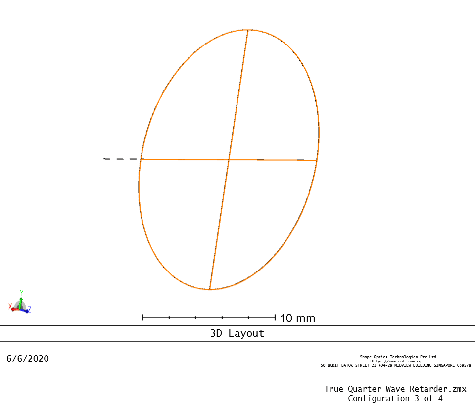
Waveplates, also known as retarders, transmit light and modify its polarization state without attenuating, deviating, or displacing the beam. They do this by retarding (or delaying) one component of polarization with respect to its orthogonal component.
Fast Axis and Slow Axis – Light polarized along the fast axis encounters a lower index of refraction and travels faster through waveplates than light polarized along the slow axis. Retardation describes the phase shift between the polarization component projected along the fast axis and the component projected along the slow axis. Retardation is specified in units of degrees, waves, or nanometers. One full wave of retardation is equivalent to 360°, or the number of nanometers at the wavelength of interest.
Zero-order wave plates have a total retardation of the desired value without any excess. Zero-order waveplates are not as sensitive to wavelength and temperature variation as multiple-order waveplates.
This example describes how to construct an effective zero-order retarder with a λ/4 phase change, also known as a quarter-wave plate, which will convert linearly polarized light to circularly polarized light. It utilizes the birefringent material quartz and a HeNe laser (632.8 nm).
Generally, the retardance of the plate is given by:

where ∆n is the difference in refractive index between ordinary and extraordinary modes, λ is the wavelength of light, d is the length of the crystal, and Γ is the retardance in radians. The variable m is a natural number which represents the order of the wave plate. With this definition, the relative phase change is not affected by the order due to the 2π periodic nature of light. That said, higher-order wave plates are physically thicker than lower order-wave plates, they are more vulnerable to thermal expansion, have amplified error in retardance for off-axis beams, and have amplified error for retardance if wavelength differs from the designed value.
To build such a true o order plate component in OpticStudio, the Lens Data Editor should appear something like the following.


In practice, few true zero-order wave plates are produced because the required crystal widths are too thin and delicate for manufacturing. Instead, effective zero-order wave plates are made from two thicker uniaxial crystals (usually of the same material) with crossed crystal axes. These are not as effective as a true zero-order wave plates, but as they are more easily manufactured, they offer a good compromise between performance and manufacturability.
To build such a component in OpticStudio, the Lens Data Editor should appear something like the following.


Hope it will help, if you need design file, please look for us.
- https://www.zemax.com/
- Zemax Optical Design Program User’s Guide, Zemax Development Corporation
- https://en.wikipedia.org/wiki/Main_Page
