In optics, polarized light can be described using the Jones calculus, discovered by R. C. Jones in 1941. Polarized light is represented by a Jones vector, and linear optical elements are represented by Jones matrices.

It is important to note that the Jones matrix does not define what happens to the Ez component. This assumes therefore that rays land at normal incidence, i.e. that the idealized polarizer is being placed in a collimated beam. This is a reasonable assumption: most polarizers and waveplates are indeed used in collimated beams or in beams with only small divergence angles.
If the beam is collimated and normal to the Jones matrix, then because k • E = 0 and the vector k has components {0, 0, 1} then Ez must be zero and we can specify the polarization purely in terms of Ex and Ey. If rays land with some arbitrary {l, m, n} then OpticStudio will adjust either Ez or {Ex, Ey} such that k • E = 0 and the magnitude of E does not increase. The adjustment may however require a reduction in the magnitude of E, and thus an associated loss of transmitted energy.
The Jones matrices are operators that act on the Jones vectors defined above. These matrices are implemented by various optical elements such as lenses, beam splitters, mirrors, etc. Each matrix represents projection onto a one-dimensional complex subspace of the Jones vectors. The following table gives examples of Jones matrices for polarizers:

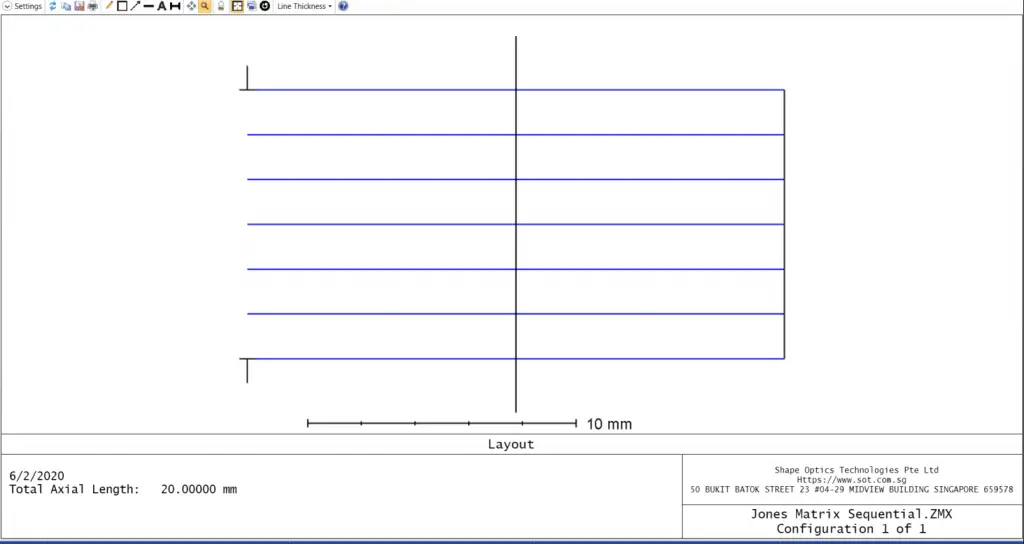
Here is an example of a Jones Matrix surface being used as a quarter wave plate. The sample file is included as an attachment to this article.

The easiest way to see the effect of the Jones Matrix surface is with the Polarization Pupil Map.
Polarization Pupil Map Generates a graph of the polarization ellipse as a function of pupil position. This aids in visualizing the change in polarization over the pupil. This feature may also be used to compute transmission in systems modeled using interfering paths in separate configurations, such as birefringent polarizing beam splitters and interferometers.

It can be seen that the input circular polarization has been altered to a linear polarization, with 100% efficiency.

If we set up the Jones matrix as an x-analyzer (Areal = +1, all other elements zero), then only x-polarized light is passed, and the transmission (naturally) falls to 50%
Reference:


