Birefringent effects are utilized in a myriad of optical systems over a wide array of fields, we share the ways to design and simulate birefringent effects such as Polarization Pupil Map, Jones Matrix, Birefringence, surface coatings and more

Input polarizations can be generated using the X-Axis, Y-Axis, or Z-Axis reference in Zemax. These references are used to translate the inpute state (Jx, Jy) into a 3-D electric field vector (Ex, Ey, Ez). From there, polarization-dependent media may be modelled in Sequential Mode through the use of:
- Jones Matrix surfaces
- Surface Coatings
- Birefringent In/Out surfaces
This article will describe setting up a polarized system as well as the pros and cons of each of the above surfaces/surface settings.
Generating a polarized light source
Input polarization states are entered into Zemax in two ways. The first is by explicitly defining the initial polarization state (Jx, Jy, and X/Y Phase) in individual analysis settings, such as with the Polarization Ray Trace and Polarization Pupil Map.

The second method is to apply the polarization state in the ‘Polarization’ section of the System Explorer. The state entered here will be considered in the calculations for any applicable analysis windows by checking the “Use Polarization” setting (or similar) in the individual analysis settings.

Polarization Pupil Map
For almost all systems, it is not important whether Zemax looks forward in time or backward in time for this calculation, because it assumes that the system is at steady-state. By default, the calculation looks forward in time (i.e. at the phase of the ray that “will hit” the specified surface if the system were to advance forward in time by some small amount).
Additionally, when defining the initial phase shift between Jx and Jy, a positive value for the “X-Phase“ or “Y-Phase” will result in Jx lagging spatially with respect to Jy, and vice versa. For example, defining X-Phase = 90 degrees and Y-Phase = 0 degrees will cause the Ex component of the electric field to lag 90 degrees behind the Ey component (see below)


Assuming that (Jx, Jy) = (0.707,0.707), the resulting polarization ellipse will be clockwise, circularly polarized, as seen by the Polarization Pupil Map.

Types of polarization-dependent media
Jones Matrix
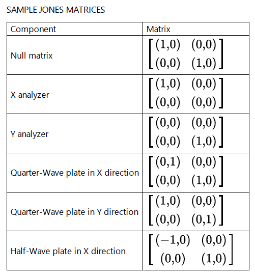
If rays are indeed aligned with the Z-axis of the system, this surface can provide an ideal simulation for relative phase change between S and P states, as well as transmission of S and P states.
Zemax will allow users to apply the Jones Matrix surface to oblique angles of incidence, but the results in this configuration will represent, by definition, an approximation.
Jones matrices that describe retarders should not be used with oblique incident angles. To accurately calculate off-axis relative phase change, the Birefringent In and Birefringent Out surfaces should be used.
Surface coatings
When polarized light is incident upon a surface, the S- and P-polarization states are defined relative to that surface. If there is a coating applied to that surface, the portion of light transmitted may change significantly depending on the reference Method defined in the System Explorer.
Here is an example in the coating design:

Birefringent In/Birefringent Out
With this approach to defining the birefringent media, the Birefringent In/Out surfaces allow users to calculate Fresnel coefficients and absorption to give a much more accurate intensity transmission calculation, as compared to the Jones Matrix surface. That is, users can optionally trace the ordinary or extraordinary beam independently or trace one while accounting for the phase rotation due to the other. This is governed by the Mode Flag, and it allows users greater flexibility in how they model birefringent effects based off the angular deviation between the ordinary and extraordinary beams for a given system.
Reference Source:
- https://www.zemax.com/
- Zemax Optical Design Program User’s Guide, Zemax Development Corporation
- https://en.wikipedia.org/wiki/Main_Page
