Stray light is any light that reaches the image plane outside the intended optical path, degrading image contrast, introducing ghosting, or reducing signal-to-noise ratio. Identifying and mitigating stray light during the design stage is critical—long before physical prototyping.
This article demonstrates a practical workflow for observing stray light using a 210° wide-angle imaging system as an example. The design file used in this demonstration can be downloaded at the end of the article.
Why Stray Light Matters
Stray light can reach the image plane through several mechanisms:
- Scattering from mechanical structures or optical surfaces
- Multiple reflections between lens elements (ghost paths)
- Light entering from outside the nominal field of view
- Light from inside the field of view undergoing secondary or tertiary reflections
These effects are difficult to evaluate in purely sequential optical models, making non-sequential analysis essential.

Step 1: Lock Down the Sequential Design
Before converting the system to Non-Sequential Mode, it is important to lock down the design using the Design Lockdown tool. This ensures:
- Lens positions and spacings reflect real manufacturing conditions
- Apertures, stops, and coatings are fixed
- Analysis results remain physically meaningful
This step avoids misleading stray-light results caused by unconstrained degrees of freedom.
Step 2: Export Critical Rays in Sequential Mode
Before switching to Non-Sequential Mode, export the critical ray set, including:
- Chief rays: Travels from a specific field point, through the center of the entrance pupil, to the image plane
- Marginal rays: Travels from the center of the object, through the edge of the entrance pupil, to the image plane
Exporting these rays allows direct verification later that the imaging function is preserved after conversion.
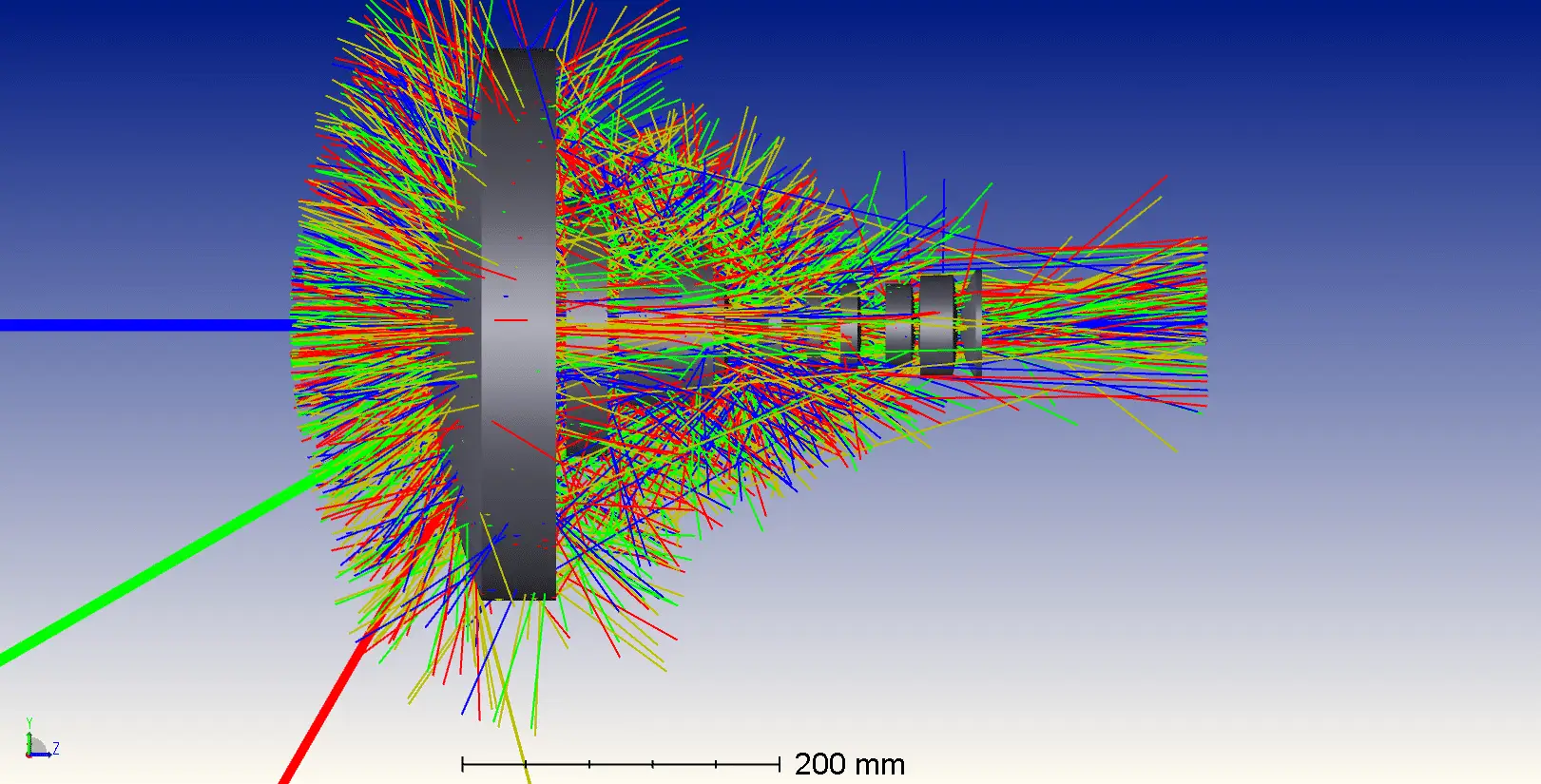
Step 3: Convert to Pure Non-Sequential Mode
After conversion:
- All lenses are transformed from surfaces into solid objects
- Light sources and detectors are automatically created to represent field points and image locations
- The non-sequential system is optically equivalent to the original sequential design
At this stage, the system geometry is identical—but now supports full ray splitting, scattering, and multiple reflections.

Step 4: Enable Ray Splitting to Reveal Stray Paths
Enable Split NSC Rays.
This is a crucial step, as it allows:
- Partial reflection and transmission at every optical surface
- Visualization of ghost reflections
- Tracking of rays that would be invisible in Sequential Mode
This capability is essential for identifying real stray-light mechanisms.
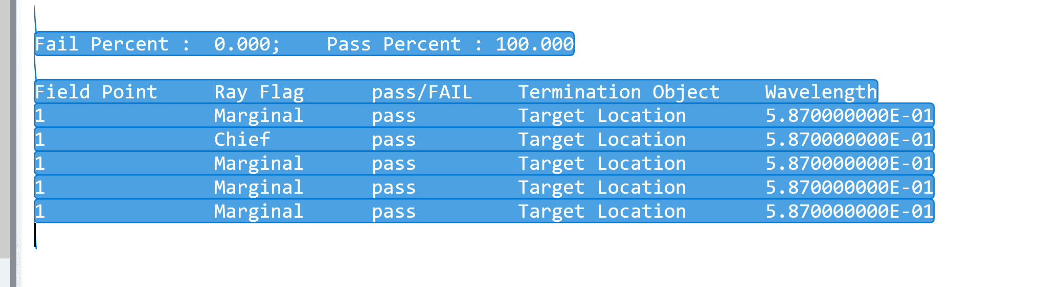
Step 5: Verify the Critical Ray Set
Check that the exported chief and marginal rays propagate correctly through the non-sequential system.
This ensures:
- The imaging path is not blocked
- Optical performance is preserved
- Mechanical components (including imported CAD geometry) do not vignette the primary ray set
If mechanical parts are added later, this verification should be repeated.
Step 6: Configure Ray-Tracing Limits for Stray Light
Stray-light rays may undergo many reflections and scatter events, so ray-trace limits must be increased:
- Maximum Intersections per Ray: 4000
- Maximum Segments per Ray: 2,000,000
If these values are too low, important stray paths may terminate prematurely and remain undetected.
For preliminary analysis, reduce:
-
Analysis Rays: 5000
This balances visibility and computation time.
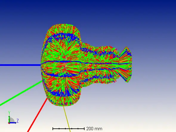
Step 7: Observe Stray Light Behavior
After tracing rays, stray light becomes visible as sky-blue “snowflake-like” points distributed throughout the system. These represent rays that:
- Undergo multiple reflections
- Scatter from surfaces
- Eventually reach or approach the image plane
These visual cues immediately highlight problematic regions requiring:
- Baffles
- Surface blackening
- Coating changes
- Geometry modification
Reference Source
- https://www.zemax.com/
- The design file used in this article is attached. How to analyse the stray light in an imaging system-PROD-NONSEQ