An off-axis parabolic mirror has the advantage of not having to obscure the input beam to access the image plane. This article will show you how to design an off-axis parabolic mirror. The concept shown here applies to any decentered surface and is not limited to off-axis parabolic mirrors.
Parabolic mirror design specifications
We will design a commercially-available off-axis parabolic mirror. The goal of this exercise is to be able to tilt the mirror about the X axis at any point along the optical axis (Z axis). The specifications for the mirror are as follows.
| Off-axis Distance | 150mm |
| Focal Length | 1000mm |
| Component Physical Diameter | 203mm |
Back surface of the substrate is perpendicular to the optical axis.
Entering the basic geometry
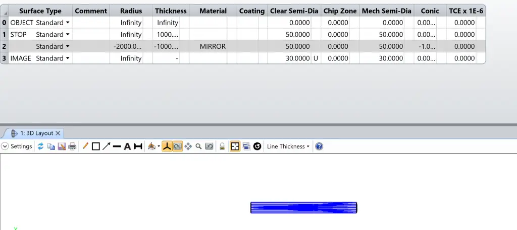
To start the mirror design, we will first define the system settings. Make the following adjustments in the System Explorer.
- Set Aperture…Aperture Type: Entrance Pupil Diameter and Aperture Value: 100
- Set Units…Lens Units: Millimeters
- Set Wavelengths…Wavelength 1: 0.550 um
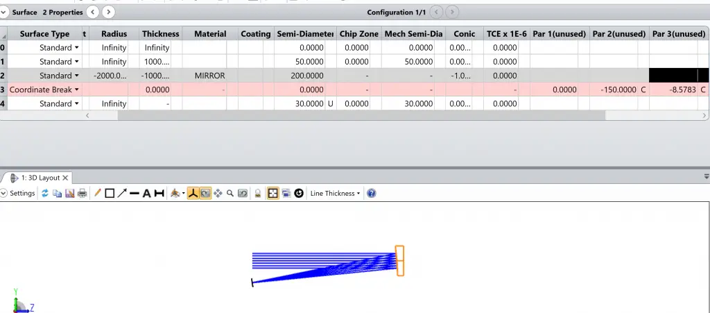
Next, we can begin defining the system geometry. Add one surface to the Lens Data Editor after the STOP surface. Then enter the following parameter values on Surfaces 1-3. Note that the Image surface has a user-defined Semi-Diameter of 30 mm, as indicated in the solve box.
The “sag” or z-coordinate of the Standard surface is given by:

where c is the curvature (the reciprocal of the radius), r is the radial coordinate in lens units and k is the conic constant. The conic constant is less than -1 for hyperbolas, -1 for parabolas, between -1 and 0 for ellipses, 0 for spheres, and greater than 0 for oblate ellipsoids. To make the mirror surface parabolic, enter Conic: -1.
Because the focal length of a mirror is half the radius of curvature in the parabolic mirror, enter Radius: -2000 mm. The sign of the radius of curvature is negative since the center of curvature is to the left (toward -Z-axis) of the parabolic mirror. Additionally, because Surface 1 and the image surface are co-located, we will choose not to draw Surface 1 in the layout so that we can see only the image surface at that location.
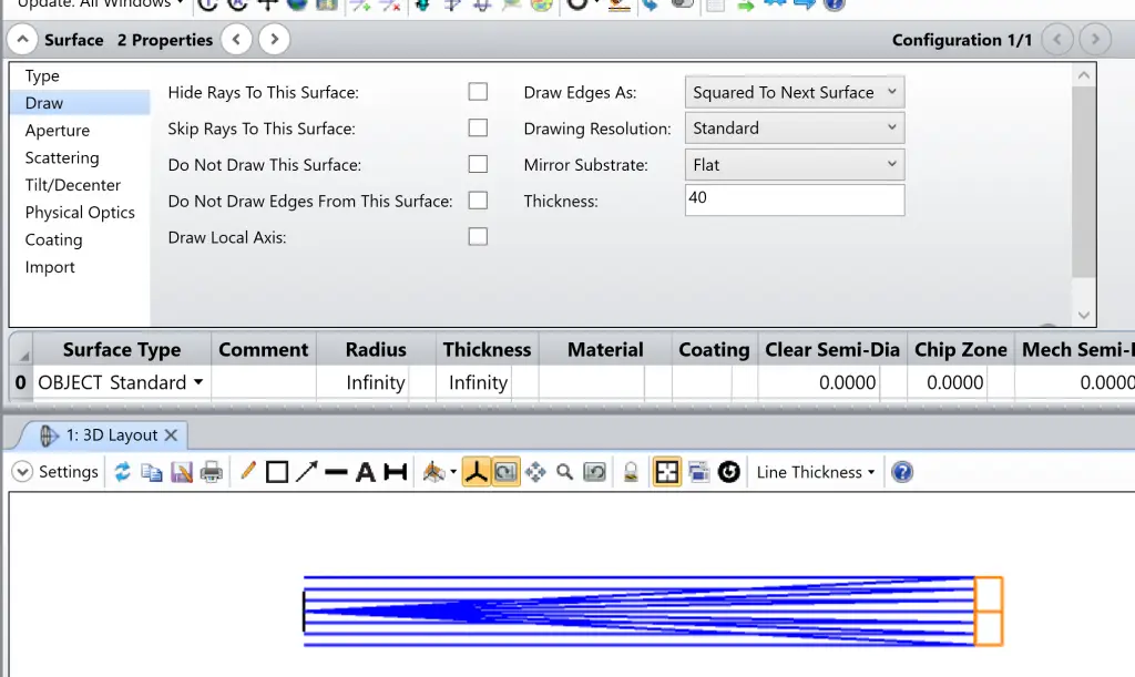
To make the mirror substrate flat and orthogonal to the optical axis, choose the following options in the Surface Properties dialog. We will set Thickness: 40 mm
Add the off-axis distance
In the Tilt/Decenter tab of Surface Properties of Surface 2, specify Decenter Y: -150 mm.
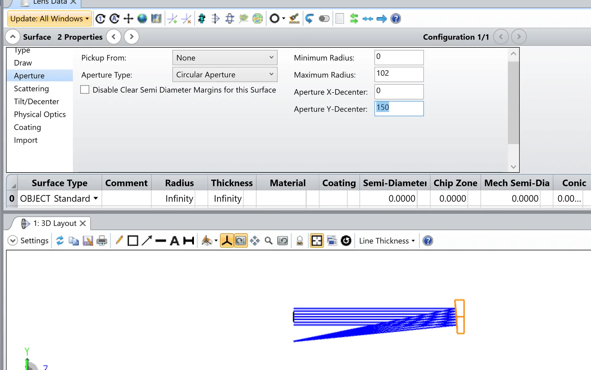
Note that the rays are moving away from the coordinate system. In order to center the image surface and make it orthogonal to the chief ray, insert a Coordinate Break surface before the image surface and place a Chief Ray solve on the Decenter Y and the Tilt About X parameters. the parabolic mirror setting will automatically calculate the amount of decenter and tilt needed to make the chief ray hit at the center of this surface at normal incidence.

