Nonlinear optics is the branch of optics that describes the behavior of light in nonlinear media, this article will share how to test whether a nonlinear optics double-pass system is correctly set up or not, and to identify where any errors are.

In sequential mode, rays are traced from one surface to another in a specific order. This means that modeling a double pass system requires that the optical system be modeled twice; once for each pass. Different solve types, such as position and pickup, should be utilized, as they are essential for making sure that the optics are mapped appropriately for the return path of the beam. Great care should be taken to ensure the model has been setup correctly – especially for tolerancing or whenever there are tilted or decentered components – because the return path must be identically perturbed compared to the first pass.
In this example, we will show a nonlinear optical double-pass system, to check if this aberration is correct, and not just an artifact of some setup error we made?
Now, let’s use the double pass tool to change the nonlinear optics system to a double pass configuration. Please refer to the article:
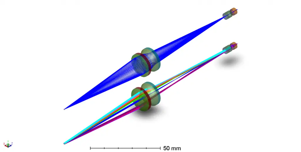
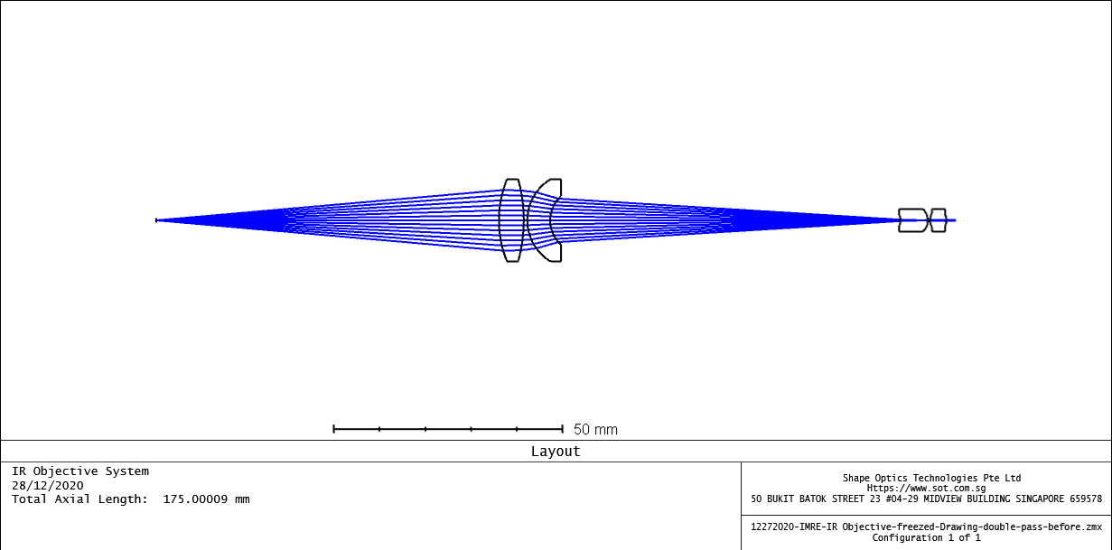
The system performance is presented as below:

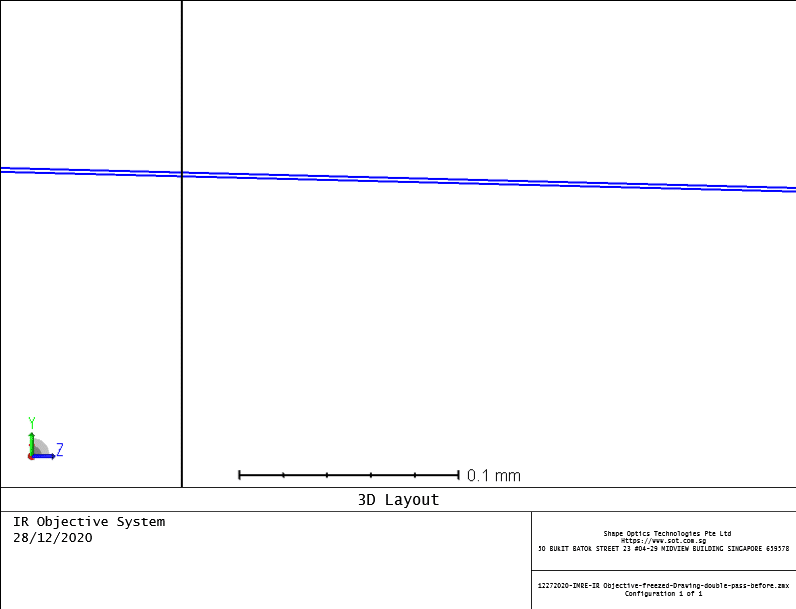
Zoom into details:
OpticStudio supports a ‘Retro Reflect’ surface type which acts like a plane mirror except that instead of reflecting rays using Snell’s law, rays are reflected exactly back along the path they came in on. Therefore, on the second path the ray should follow the exact path it came in on. This means that it should be re-imaged to a perfect, unaberrated spot. 

With this surface type selected, the aberrations are cancelled on the second pass, resulting in a perfect point image.
Even better, if you have made some mistake and you do not see perfect aberration correction, you can use Analysis…Rays & Spots…Single Ray Trace to trace a ray. The ray-trace data should be exactly the same on either side of the Retro Reflect surface, and when you identify a pair of surfaces that are not exactly the same, you have identified the setup problem:

As you could see, surface 9 and surface 14, the angle and position is exactly the same.
When tolerancing, do a test tolerancing run of the nonlinear optics double-pass system in which the double-pass mirror is made a retro-reflector and tolerance for RMS spot size. If your system and tolerance operands are correctly set up, no matter what the tolerances are, the tolerancing criterion should be identically zero for all operands and all Monte-Carlo files. Any non-zero results indicate setup errors in either the lens itself or the tolerance operands.
Reference Source:
- Laikin, Milton. Lens Design. CRC Press, 2007.
- https://www.zemax.com/
- Zemax Optical Design Program User’s Guide, Zemax Development Corporation
- https://en.wikipedia.org/wiki/Main_Page
