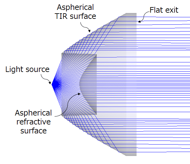
This article introduces the fundamentals of nonimaging optical systems, focusing on the background concepts and basic theory behind nonimaging optics design. Nonimaging optics plays a critical role in illumination engineering, where the goal is not image formation but efficient and controlled light distribution.
Background: What Is Nonimaging Optics?
Nonimaging optics—often implemented using non-sequential ray tracing—is widely used in illumination systems such as LED lighting, backlights, projectors, and solar concentrators.
Unlike imaging optics, where the goal is to form a sharp image, nonimaging optics requires a different design mindset:
- The objective is optimal transfer of light from a source to a target
- Image quality metrics (MTF, resolution) are replaced by efficiency, uniformity, and angular control
- Rays may reflect, refract, scatter, or undergo total internal reflection in complex paths
The primary goal of a nonimaging optics design is to map the light emitted by a source into a desired spatial and angular distribution at the target. At the same time, practical constraints such as color performance, cost, size, and manufacturability must be considered—although these factors are often more difficult to express directly in a mathematical merit function.

Fundamental Concepts in Nonimaging Optics Design
Units of Measure
A solid understanding of radiometric and photometric quantities is essential in nonimaging optics. Below is a shorthand table for quick reference:
| Quantity | Symbol | Radiometric Name | Units | Photometric Name | Units |
|---|---|---|---|---|---|
| Flux | Φ | Radiant power | W | Luminous flux | lm |
| Flux / Area | E | Irradiance | W/m² | Illuminance | lm/m² (lux) |
| Flux / Solid Angle | I | Radiant intensity | W/sr | Luminous intensity | lm/sr (cd) |
| Flux / (Area·Solid Angle) | L | Radiance | W/m²·sr | Luminance | lm/m²·sr (cd/m², nit) |
Note: Symbol usage is not universal. Radiometric quantities may also be denoted by P, H, J, or N, while photometric quantities may use F, E, I, or B, depending on the reference.
Point Sources
Some light sources are small compared to the optical system and can be approximated as point sources. This simplification enables:
- Faster calculations
- Easier interpretation of angular distributions
- Simplified efficiency analysis
Point-source approximations are commonly used in early-stage illumination design.

Defining Energy: Encircled Energy
In nonimaging optics, encircled energy is a fundamental reference when calculating system efficiency.
Encircled energy represents the fraction of total emitted power contained within a defined angular or spatial region. For example, in an LED system, efficiency is often evaluated by comparing:
- Energy emitted by the source
- Energy captured and delivered to the target
Encircled energy provides a consistent baseline for these calculations.


TIR Lenses and Energy Collection
A common nonimaging optical element is the Total Internal Reflection (TIR) lens.
- The front surface refracts light
- The side surfaces reflect light via total internal reflection
- The combination enables high-efficiency light collection and redirection
TIR lenses are widely used in LED collimators and flood optics due to their compact size and excellent efficiency.

Uniform Distribution and Energy Conservation
One of the central principles of nonimaging optics is the conservation of energy (étendue conservation).
In the example shown:
- The source emits a Gaussian intensity distribution
- The nonimaging lens redistributes this energy into a flat (top-hat) distribution at the target
This transformation improves uniformity while conserving total energy, a hallmark of good nonimaging optical design.

Conclusion
Nonimaging optics focuses on how light is distributed, not how images are formed. By understanding radiometric quantities, encircled energy, point-source approximations, and elements such as TIR lenses, designers can create highly efficient illumination systems that meet real-world requirements.
These foundational concepts underpin advanced topics such as freeform optics, illumination optimization, stray light control, and non-sequential ray tracing.
References
