The Bio-fluorescence describes the process by which light is absorbed within an object and then re-emitted at a different (usually longer) wavelength. How to design it, here we share some tips.

An example as below ( attached in the end of this article) has been setup to illustrate modeling of a Bio-fluorescent object . In this simple system, a Source Ellipse is used to launch a collimated beam of rays towards a volumetric object in which bulk scattering may occur.

In this example, when a ray is bulk material scattering inside object 2, its wavelength is also shifted from wavelength 1 to wavelength 2. Look at Object 2’s properties, in the Bulk material Scattering tab. The wavelength-dependent beamsplitter separates the two wavelengths out. The second layout plot uses the X_Waveshift(1,2) filter string to show only those rays that have shifted in wavelength.
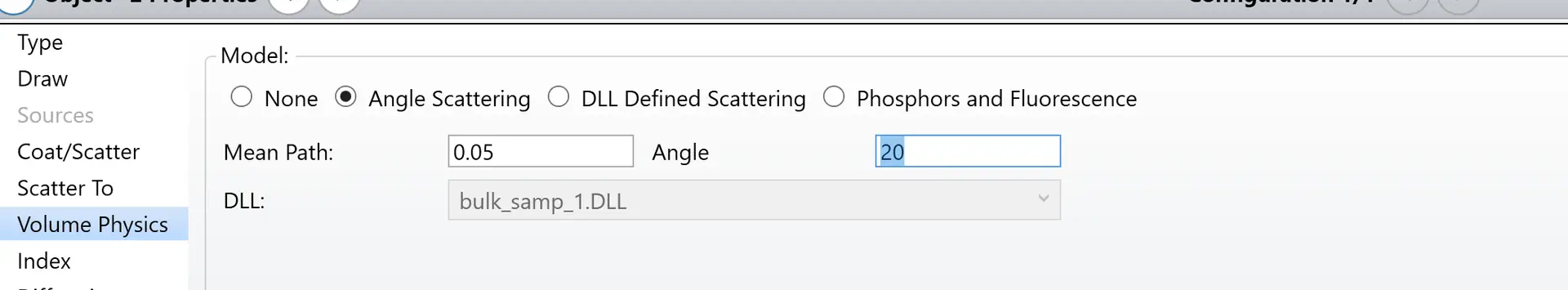
Within the volume, bulk material scattering occurs according to the Angle Scattering distribution, with a mean free path of 0.05 mm and a maximum angle for scattering of 20 degrees:
In this simple Bio-fluorescence material scattering example, rays that start out with wavelength #1 will be shifted to wavelength #2 with a 100% probability, i.e. all of the input rays (with a wavelength of 0.780 um) that undergo bulk scattering will also undergo a wavelength shift (to 0.900 um). In general, inputs to the Wavelength Shift box are not restricted to a single wavelength transition, and not all rays which undergo bulk scattering are required to undergo a wavelength shift.
To test that the “Wavelength Shift” tool is working correctly, another rectangular volume object is included in the file, which has on its front face the BEAMSPLIT table coating:
TABLE SBICBEAMSPLIT
ANGL 45.0
WAVE 0.78 1.0 1.0 0.0 0.0 0.0 0.0 0.0 0.0
WAVE 0.90 0.0 0.0 1.0 1.0 0.0 0.0 0.0 0.0
According to the BEAMSPLIT table coating, all rays with a wavelength of 0.780 mm will be reflected, and all rays with a wavelength of 0.900 mm will be transmitted.
As we can see in the Layout plot, all of the input rays which do not undergo Bio-fluorescence material scattering are reflected from the front face of the rectangular volume object, while all of the rays which do undergo bulk scattering are transmitted:

The design file used in this particle is attached, please download it here.How to design Bio-fluorescence material scattering
Reference Source:
- Laikin, Milton. Lens Design. CRC Press, 2007.
- https://www.zemax.com/
- Zemax Optical Design Program User’s Guide, Zemax Development Corporation
- https://en.wikipedia.org/wiki/Main_Page
