In practical optical system design, temperature variation can significantly affect performance. Changes in temperature alter refractive indices, component dimensions, and air gaps, potentially degrading image quality or alignment.
Zemax OpticStudio provides powerful thermal modeling capabilities that allow optical engineers to simulate these effects accurately. Using the Multi-Configuration Editor (MCE) and the built-in Make Thermal tool, designers can model systems operating across multiple temperature environments and implement athermalization strategies to maintain performance.
This article demonstrates thermal modeling using three optical examples and shows how to athermalize an optical design efficiently.
Thermal Effect Modeling: Flat Window Example
In this first example, the optical system consists of two flat, parallel windows illuminated by a perfectly collimated beam. Because the surfaces are flat, temperature changes only affect component size and spacing, not beam quality.
- Nominal temperature: 20 °C
- Elevated temperature: 500 °C (exaggerated for visualization)
- Window thickness: 100 mm
- Air gap between windows: 200 mm

The air space is assigned a thermal coefficient of expansion (TCE) of 23 ppm, approximating aluminum. In OpticStudio, air spaces are modeled as infinitesimally thin cylindrical spacers, which expand:
- Axially (Z-direction)
- Radially (XY-plane)

For flat windows, radial expansion does not affect spacing; however, in curved systems, it can alter center thickness due to changing contact geometry. The TCE of the glass is specified in the Materials Catalog as shown below:

Multi-Configuration Thermal Setup
Thermal modeling requires all temperature-dependent parameters to be defined in the Multi-Configuration Editor (MCE):
- A TEMP operand specifies the temperature per configuration
- Thermal Pickup Solves scale thicknesses and semi-diameters automatically
Configuration 1 is set to 20 °C, while Configuration 2 is set to 500 °C. OpticStudio computes the thermally adjusted values automatically.


Notice how the parameter values in Configuration 2 are automatically calculated by OpticStudio based on the temperature assigned to.

Updating the 3D Layout to display both configurations clearly shows axial expansion and the displacement of the second window at elevated temperature.

The figure above shows the effect of thermal expansion on the location of the second window. You can also notice the change in window thickness and semi-diameter values in the Multi-Configuration Editor.
Multiple Temperature Zones in One System
To model different temperatures within the same system:
- Insert an additional TEMP operand
- Assign separate temperature values to specific surfaces
For example, setting Surfaces 3 and 4 to 1000 °C while earlier surfaces remain at 20 °C results in noticeably increased thickness for those elements, accurately reflecting localized heating effects.

Notice how the thickness of Surface 3 is larger than Surface 2 in Configuration 2.
Thermal Modeling of a Cooke Triplet
Before thermal analysis:
- Remove any Marginal Ray Angle solves that modify curvature automatically.
- Enable Adjust Index Data To Environment in System Explorer → Environment
This ensures refractive indices change with temperature based on material data.

Instead of manually adding all thermal operands, use the Make Thermal tool:
- Define nominal temperature: 20 °C
- Add additional configurations at –20 °C and +60 °C
The tool automatically populates the MCE with all required operands and pickup solves. Toggling between configurations reveals temperature-induced performance changes in real time across analysis windows.

Besides the nominal temperature (Configuration 1), we will add configurations at -20 and +60 degrees Celsius for a total of three configurations. Insert the values in the Make Thermal Configuration window and observe the MCE as shown in figures below:


Toggle between the configurations by pressing <Ctrl + A>. You will notice changes to the analysis windows’ results due to the effect of temperature change.
Athermalizing an Optical Design
OpticStudio’s thermal modeling tools also enable athermalization, ensuring consistent optical performance across temperatures.
Cemented Doublet Example
In this design:
- Configuration 1: 20 °C
- Configuration 2: 100 °C
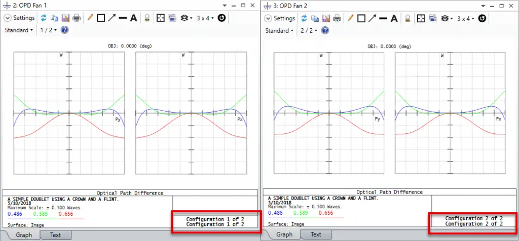
Initial OPD Fan analysis shows clear performance differences between temperatures.
First, open the attached sample file athermalization.zmx. The first configuration is the system at reference temperature of 20°C and the second at 100°C. These two configurations were defined using the Make Thermal tool. After a quick look at the OPD Fan for each configuration, we notice that the system is clearly performing differently at the two temperatures.

Athermalization Strategy
- Use glass substitution with Hammer Optimization
- Minimize RMS wavefront error difference between configurations
- Maintain effective focal length at 100 mm and the glass TCE difference to be <1 ppm (to reduce cement stress)
The Merit Function Editor includes:
- EFFL operand to lock focal length
- Operands constraining the difference in glass TCEs
- RMS wavefront error terms generated via the Default Merit Function tool

Glass Substitution Solves (marked S) allow Hammer Optimization to search for thermally compatible glass pairs from the Materials Catalog. This solve allows the glass type to change during the Hammer Optimization runs. The glasses are picked from the specified system Materials Catalogs. Remember that Hammer Optimization will be used to search for solutions that have similar forms as the starting design, and that glass substitution requires Global Search or Hammer Optimization.

To run the optimization click Optimize…Hammer Current. Feel free to stop the optimization after a few minutes. At this point, the optimized design will show almost identical OPD between the two configurations/temperatures. You can also verify that the TCE difference of thermal effects between the two glasses is less than 1 ppm, by opening the Materials Catalog.
