What is ISO 10110 Optical Drawings? SOLIDWORKS assembly files created using OpticsBuilder contain mechanical and optical components. And OpticsBuilder can create drawings of circular lenses using the Generate Lens Drawing tool. The drawing template is the framework that organizes and presents lens geometry and properties in a drawing.
This article is a step-by-step guide to understand what information is contained in a custom ISO 10110 Optical drawing template and how to create a custom drawing template for use with OpticsBuilder.
To use the drawing tool:
- Import a ZBD file into OpticsBuilder
- Save the imported lenses to a SOLIDWORKS assembly
- Click Generate Lens Drawing
- Select the optical components to generate drawings for (see Figure 2)
- Select shapeoptics drawing template
- Click the green check mark to start the drawing tool
Figure 1 shows the Generate Lens ISO 10110 Optical Drawing icon circled in red.
 Figure 2 shows the Generate Lens Drawing Tool dialog box.

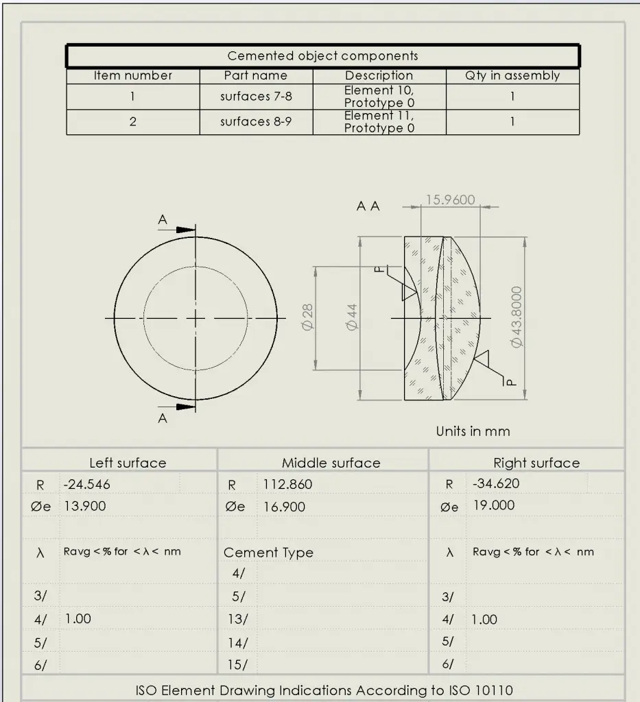
After the drawing tool is started drawings are created of lens front and cross-section views. Dimensions are added for lens thickness and face diameters. If we selects the Shapeoptics template in the drawing tool the drawing will appear as shown in Figure 3. The SOLIDWORKS template is not customized for optical drawings although lens data may be brought into the template for drawing generation.

Figure 3. OpticsBuilder ISO 10110 Optical Drawing Template
When using the OpticsBuilder template the following data is automatically populated in the drawing table if it exists in the ZBD file:
- Lens radius of curvature with sign to indicate concave or convex (R)
- Clear aperture radii (Øe)
- Lens material (Glass:)
- Refractive index with uncertainty (Nd)
- Abbe number with uncertainty (Vd)
- Power Irregularity (3/)
- Tilt (4/)
- Surface Imperfection Tolerance (5/)
- Reference wavelength (6/)
- Material Imperfections – Stress birefringence (0/)
- Material Imperfections – Bubbles and Inclusions (1/)
- Material Imperfections – Inhomogeneity and Striae (2/)
- Lens name (Part/DRAWING)
- Drawing sheet scale (SCALE)
Automating the creation of lens ISO 10110 Optical drawings is one way that OpticsBuilder streamlines the opto-mechanical design process. The framework for automating drawing creation starts with the proper creation of a custom drawing template. This article laid out the fundamentals of creating a custom ISO 10110 Optical Drawings template so that users of OpticsBuilder can integrate the Generate Drawing Tool into your workflow.
Reference Source:
- Laikin, Milton. Lens Design. CRC Press, 2007.
- https://www.zemax.com/
- Zemax Optical Design Program User’s Guide, Zemax Development Corporation
- https://en.wikipedia.org/wiki/Main_Page
