In optical systems, the performance of lenses can be significantly impacted by temperature changes. OpticStudio provides powerful tools for modeling thermal effects on optical components, such as refractive index changes and thermal expansion of materials. The Thermal Coefficient of Expansion (TCE) column in the Lens Data Editor (LDE) helps simulate these effects, particularly for the optical mounts (spacers) between lenses.
Understanding Glass Thermal Expansion in Lens Mounts
The spacer between two lenses (e.g., between surfaces 2 and 3 in the example) can be represented as an infinitely thin cylinder that connects the two lenses. This spacer has the same radial extent as the semi-diameter of the surface.
To accurately model the thermal effects on the optical system, the semi-diameter of the lens should be aligned with the radial height at which the mount contacts the lens. If necessary, a user-defined aperture can be applied to represent the actual mechanical size of the lens.
The spacer’s glass thermal coefficient of expansion (TCE) is defined in the TCE column of the LDE. The spacer will expand or contract with temperature, affecting the center thickness between the lenses. The spacer will expand both radially (X and Y axes) and axially (Z axis).

Spacer Behavior at Nominal Temperature
At nominal temperature, the semi-diameters of the spacer and contacting lens surfaces are the same. However, if the TCE values of the spacer and the lenses are different, they will expand or contract at different rates, causing changes in the center thickness of the system. This is particularly important for high-precision applications.
In the example, the spacer contacts the lenses at different radii (80 mm at surface 2 and 100 mm at surface 3). The expansion of the spacer and lenses will result in changes to the center thickness between the lenses as temperature changes, which can be monitored and calculated using OpticStudio.


The following animation shows the spacer and the lenses expanding at a different rate (different TCE).

If the TCE of the spacer is set to zero, the length of the spacer does not change with temperature, as shown in the animation below. However, even with zero spacer TCE, the center thickness between the two glasses will change if the radius of any two contacting glass surfaces change with temperature. Observe how in the animation below the center thickness changes while the length of the spacer (highlighted in red) remains fixed.

Numerical Example: Zero TCE for Spacer
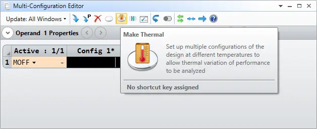
In a system with a zero TCE spacer, the spacer’s dimensions remain constant regardless of temperature. This can be simulated using the Make Thermal tool in the Multi-Configuration Editor.
At 20°C (initial temperature), the semi-diameters of the spacer and lenses are set to 80 mm and 100 mm, respectively. When the temperature increases to 120°C, the radiuses of curvature of the lenses change, but the spacer length remains constant.

This system assumes that the TCE value for the spacer between the lenses is zero. As shown on the previous page, the center thickness between the lenses still changes with temperature, since the radii of curvature of each lens changes with temperature. We will calculate the new center thickness value explicitly.
When the TCE value for the spacer is zero, the spacer thickness will remain fixed. The spacer thickness is the distance from the maximum radial aperture of back surface of the first lens to the maximum radial aperture of the front surface of the second lens. This is the case because the radial aperture of the spacer is assumed to be the same as the radial aperture of each of the lens surfaces at the default temperature (20°C). Thus, the radial aperture of the spacer is 80 mm at surface 2 and 100 mm at surface 3.
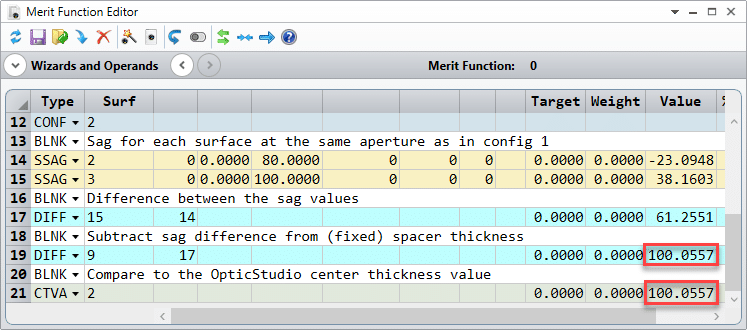
The value for the spacer thickness can be calculated from the sag values of each surface and the center thickness between the surfaces at 20°C (configuration 1). Such a calculation is provided in the first part of the merit function, and the result shows exact agreement with the value for the edge thickness obtained from the ETVA operand:

In configuration 2, the temperature has increased to 120°C, so the radial aperture of each lens surface has also increased. Conversely, the radial aperture of the spacer does not increase, since the TCE value for the spacer is zero. Thus, the spacer thickness is still evaluated using a radial aperture of 80 mm on surface 2 and 100 mm on surface 3. However, since the radii of curvature change with temperature, the sag of each surface at these radial coordinates is different.
Using the new surface sag values, we can calculate what the new center thickness between the lenses must be, in order to maintain the same spacer thickness. This calculation is provided in the second part of the merit function, and the results show exact agreement with the value for the center thickness obtained from the CTVA operand:
Numerical Example: Finite TCE for Spacer
The calculation for the center thickness between the lenses becomes even more complicated when a finite value for the spacer TCE is used.
In this example, the TCE value for the spacer is set to 23.6 x 10⁻⁶ C-1, which is the standard value for aluminum. Since the TCE value for the spacer is larger than that for the glass (7.1 x 10⁻⁶ C-1 for N-BK7), the radial aperture of the spacer will expand by a larger amount than the aperture of each lens surface as the temperature goes from 20 to 120°C.
The first part of the merit function is again dedicated to calculating the spacer thickness at 20°C. In the next part of the merit function, we calculate the multiplication factor that will be used to scale the radial aperture values for the spacer and the lens surfaces:

The values for the new radial apertures (spacer and lenses) are then calculated, along with the sag of the lens surfaces at each aperture value:

We see that the spacer apertures expands to 80.189 mm and 100.236 mm at surfaces 2 and 3, respectively, while the lens apertures expand to 80.057 mm and 100.071 mm at each of these surfaces. In the previous section, we used the spacer apertures to define the spacer thickness, because the spacer apertures were smaller than the lens apertures. In this case the reverse is true, so the lens apertures will be used to define the new spacer thickness.
At the radial aperture to which the spacer expands, the new spacer thickness is:
- Spacer thickness @ spacer apertures = (Spacer thickness @ 20°C)*(1 + TCE*DT)
- Spacer thickness @ spacer apertures = 161.311*(1 + 23.6 x 10⁻⁶ C-1*100°C) = 161.692 mm
However, as we just indicated above, the spacer thickness needs to be evaluated at the lens apertures, since these are smaller than the spacer apertures. In this case, the spacer thickness at the lens apertures is given by:
- Spacer thickness @ lens apertures = Spacer thickness @ spacer apertures – (D1 – D2)
- D1 = Sag of surface 2 @ lens aperture – sag of surface 2 @ spacer aperture
- D2 = Sag of surface 3 @ lens aperture – sag of surface 3 @ spacer aperture
From the merit function, we find that:
- D1 = -23.131 mm – (-23.214 mm) = 0.083 mm
- D2 = 38.224 mm – 38.372 mm = -0.148 mm
- D1 – D2 = 0.083 mm – (-0.148 mm) = 0.231 mm
- Spacer thickness @ lens apertures = 161.692 mm – 0.231 mm = 161.461 mm
This is exactly the calculation performed in the third part of the merit function, and the results show exact agreement with the edge thickness value obtained from the ETVA operand (the values are slightly different from my calculations above due to round-off error):

The center thickness value between the lenses is again calculated from the edge thickness and the sag values of the surface, this time at the lens apertures:

Again, exact agreement is found between our calculation and the result obtained in OpticStudio with the CTVA operand.
Conclusion
Thermal expansion plays a critical role in the performance of optical systems, especially when lenses are mounted with spacers that may expand or contract with temperature. By modeling the TCE values of these components in OpticStudio, you can predict and correct for any changes in center thickness or optical alignment, ensuring the system’s accuracy and performance across varying temperature conditions.