This article is intended as an introduction for new users working with Code-V OpticStudio.
Using a simple singlet lens design as an example, we will walk through the fundamental steps of:
- Defining system specifications
- Understanding the Lens Data Editor (LDE)
- Setting fields and wavelengths
- Applying constraints using solves
- Preparing the system for optimization
This example provides a foundation for more advanced optical design workflows.
Design Prescription and Constraints
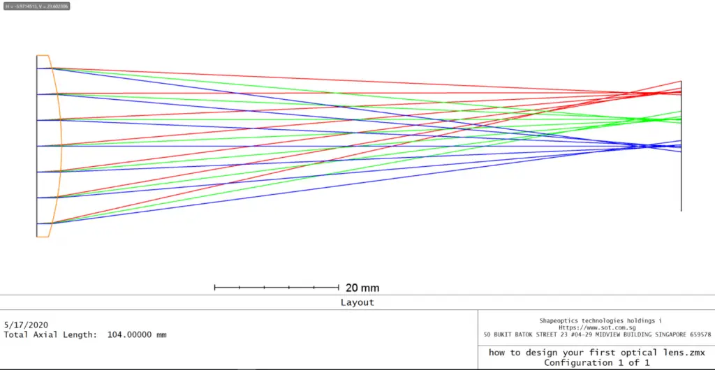
In this exercise, we design and optimize an F/4 singlet lens made of N-BK7 glass.
The design must satisfy the following specifications:
| Specification | Constraint |
|---|---|
| Focal Length | 100 mm |
| Semi-Field of View (SFOV) | 5° |
| Wavelength | 632.8 nm (HeNe) |
| Center Thickness | 2 – 12 mm |
| Edge Thickness | > 2 mm |
| Optimization Criterion | RMS Spot Size (averaged over FOV) |
| Object Location | Infinity |
This is a monochromatic, infinite-conjugate imaging system, ideal for learning the basics.
The Lens Data Editor (LDE)
In Sequential Mode, rays are traced from one surface to the next in the order listed. The Lens Data Editor (LDE) is the primary workspace where most lens parameters are defined.
Some of the main entries are shown below:

Defining System Settings
Before entering lens geometry, it is best practice to define global system parameters using the System Explorer.
Setting these correctly early on helps avoid convergence issues later.

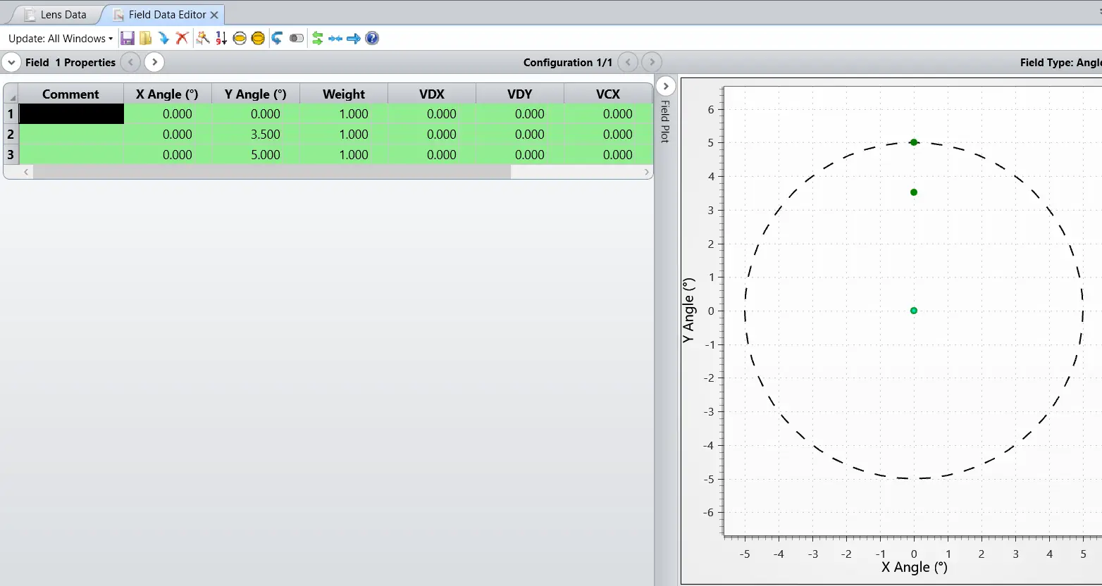
Defining Fields in OpticStudio
Field points are defined in the Field Data Editor, accessible via: System Explorer → Fields → Open Field Data Editor

OpticStudio supports five different field definition models:
| Field Type | Description | Typical Use |
|---|---|---|
| Angle (Deg) | Chief ray angle relative to object-space Z-axis | Infinite-conjugate systems |
| Object Height | X-Y coordinates on the object surface | Finite-conjugate systems |
| Paraxial Image Height | Paraxial image height on the image surface | Fixed-frame, paraxial designs |
| Real Image Height | Real ray image height on the image surface | Accurate fixed-frame systems |
| Theodolite Angle | Azimuth θ and elevation φ angles | Astronomy, surveying |
For this design:
- Field Type: Angle (Deg)
- Most appropriate for objects at infinity
Setting the Wavelengths
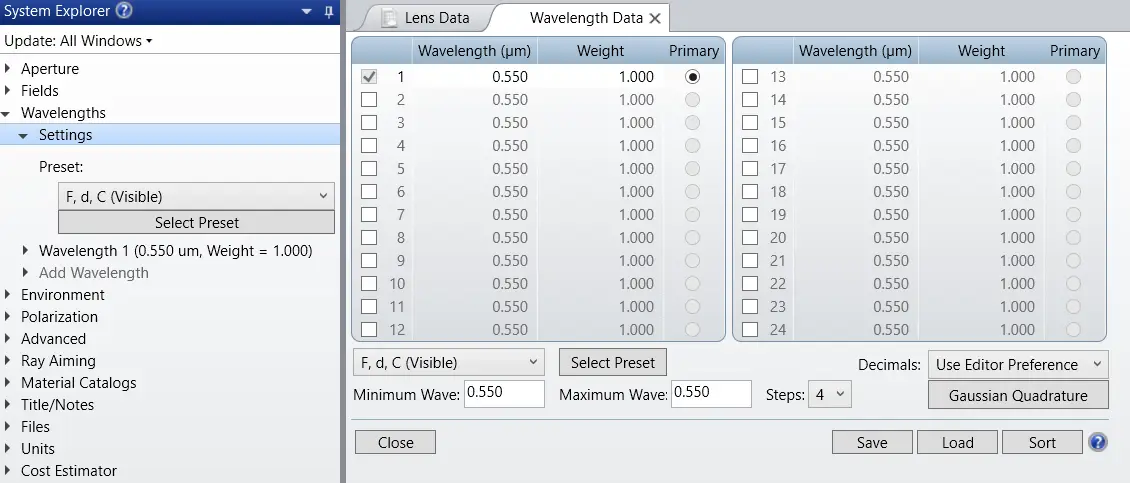
This singlet lens is designed for a single wavelength.
- Wavelength: 632.8 nm
- Source: HeNe laser
In OpticStudio:
- Open System Explorer → Wavelengths
- Enter 0.6328 µm
- Assign full weight to this wavelength

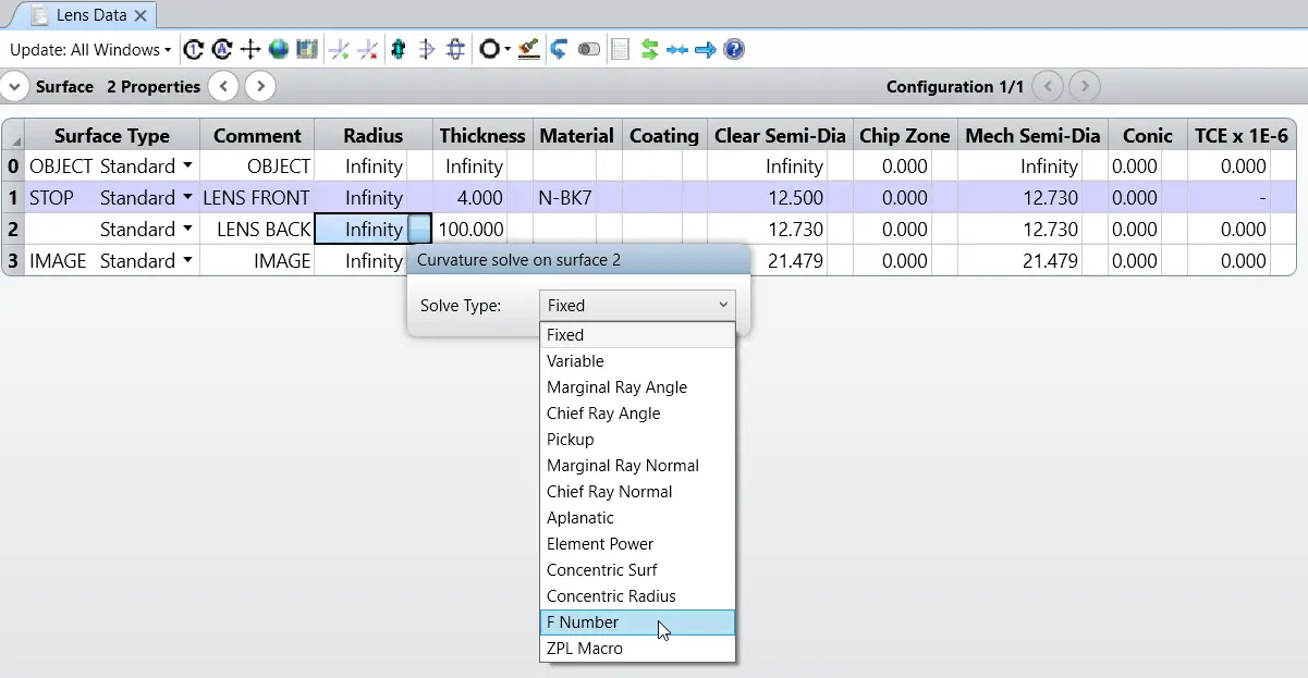
Inserting Lens Surfaces
The system stop is located at the front surface of the singlet.
Steps:
- Surface 0: Object at infinity
- Surface 1: Front surface of singlet (STOP)
- Surface 2: Back surface of singlet
- Surface 3: Image surface
Insert Surface 2 to represent the rear face of the lens.

Using Solves to Enforce Constraints
When constraints exist, there are two main approaches:
1. Merit Function Constraints
- Make parameters variables
- Enforce limits using operands in the Merit Function Editor
2. Built-In Solves (Recommended for Beginners)
- Automatically enforce constraints
- Reduce the number of free variables
- Improve optimization stability
Examples of useful solves:
- Edge Thickness Solve
- F-number or focal length solve
- Chief ray or marginal ray solves
Using solves avoids unnecessary complexity and keeps the design well-behaved.
Final Design State
If you follow the steps correctly:
- The singlet meets focal length and F-number requirements
- Thickness constraints are satisfied
- RMS spot size is minimized over the full field
- The system is ready for further optimization or analysis
This simple example demonstrates the core workflow used in almost all sequential optical designs.
