An off-axis parabolic (OAP) mirror offers a key advantage over on-axis reflective optics:
it eliminates central obscuration, allowing unobstructed access to the image plane while maintaining excellent aberration control.
In Zemax OpticStudio, an OAP mirror can be modeled by applying tilt and decenter to a parent parabolic surface.
The workflow described here applies broadly to any decentered or tilted surface, not just off-axis parabolas.
Off-Axis Parabolic Mirror Design Specifications
We will design a commercially available off-axis parabolic mirror with the following parameters:
| Parameter | Value |
|---|---|
| Off-Axis Distance | 150 mm |
| Focal Length | 1000 mm |
| Physical Diameter | 203 mm |
| Substrate Back Surface | Perpendicular to optical axis |
The design goal is to allow the mirror to be tilted about the X-axis at any position along the optical (Z) axis, while maintaining correct imaging geometry.
Step 1: Define System Settings
Open System Explorer and apply the following settings:
Aperture
Type: Entrance Pupil DiameterValue: 100 mm
Units
Lens Units: Millimeters
Wavelengths
Wavelength 1: 0.550 µm
These values establish a simple monochromatic, pupil-defined system suitable for geometric setup.
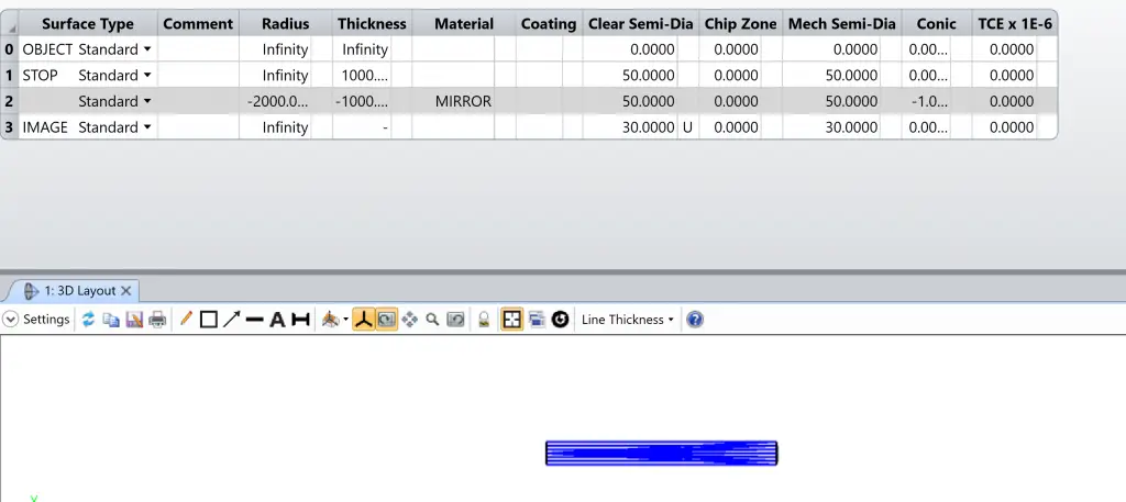
Step 2: Enter the Basic Geometry
Add one surface after the STOP surface in the Lens Data Editor (LDE).
Define Surfaces 1–3 as follows:
- The Image Surface uses a User-Defined Semi-Diameter of 30 mm
- Surface 1 is co-located with the Image surface and will not be drawn in the layout
This setup simplifies visualization while preserving correct ray behavior.
Step 3: Define the Parabolic Mirror Surface
The surface sag z of a Standard surface in OpticStudio is given by:

Where:
- = curvature (1 / radius)
- r = radial coordinate
- k = conic constant
Conic Definition
Conic constant (k): −1 → Parabolic surface
Radius of Curvature
For a parabolic mirror: f = R/2
Therefore:
- Focal length = 1000 mm
- Radius = −2000 mm
The negative sign indicates the center of curvature lies toward the −Z direction, consistent with reflective optics in OpticStudio.
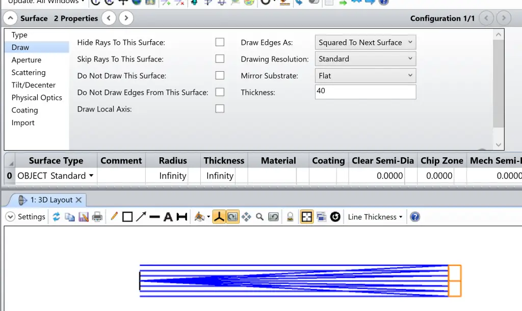
Step 4: Define the Mirror Substrate
To ensure the back surface of the substrate is flat and perpendicular to the optical axis:
Open Surface Properties and set:
- Thickness: 40 mm
- Back surface: Plano and orthogonal to Z-axis
This represents a realistic mechanical substrate while keeping the optical surface unchanged.
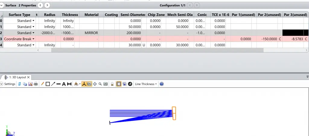
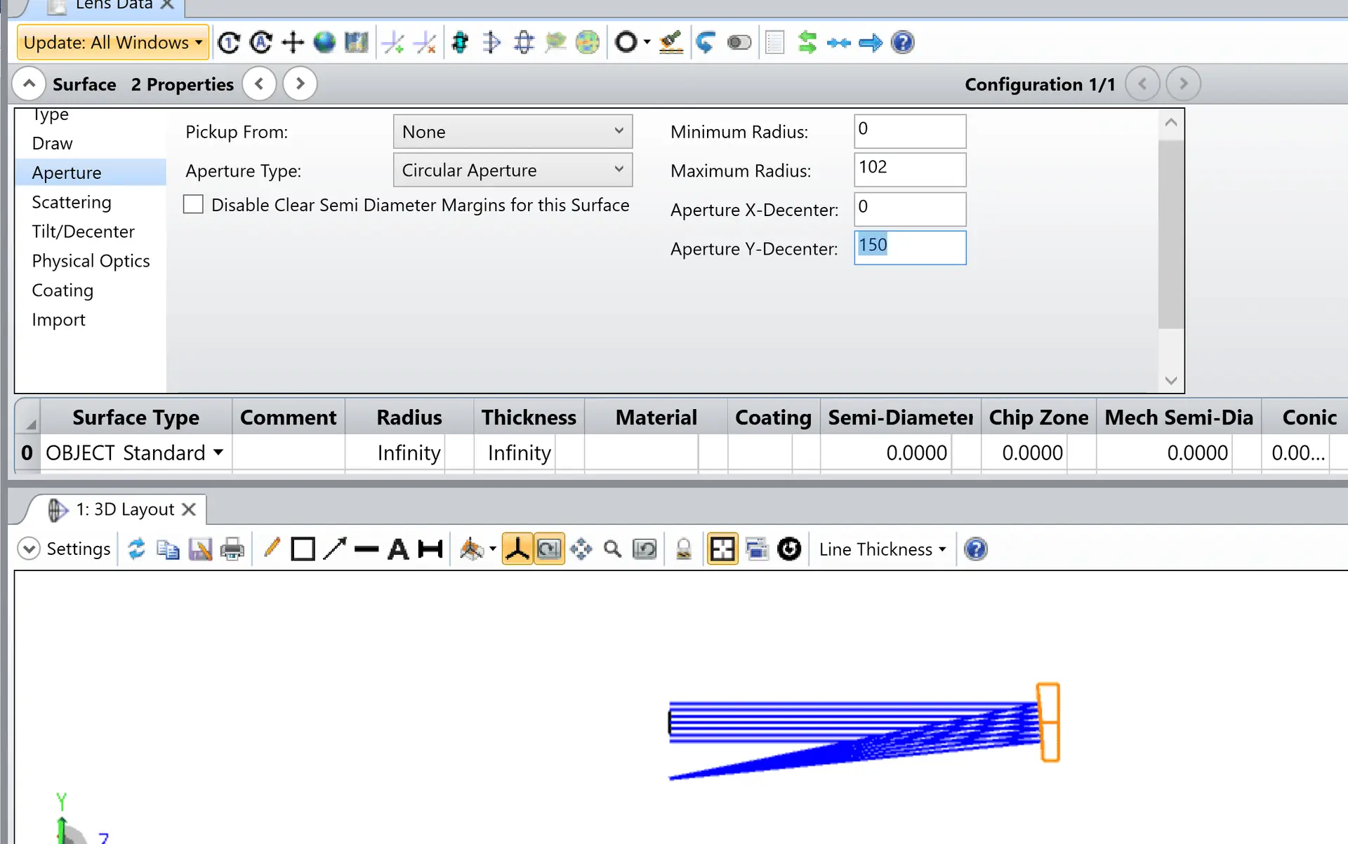
Step 5: Add the Off-Axis Distance
To create the off-axis geometry:
In Surface Properties → Tilt/Decenter (Surface 2):
Decenter Y: −150 mm
This shifts the usable portion of the parent parabola, forming the off-axis segment.
Step 6: Re-Center the Image Using a Coordinate Break
After decentering, rays propagate away from the original coordinate system.
To correct this:
Insert a Coordinate Break surface before the Image surface
Apply a Chief Ray solve to:
Decenter Y
Tilt About X
OpticStudio automatically computes the required tilt and decenter so that:
- The chief ray strikes the Image surface
- The Image surface is centered and normal to the chief ray
This ensures proper imaging geometry without manually calculating angles.

Key Design Takeaways
Off-axis parabolic mirrors are created by tilting and decentering a parent parabola
The optical performance remains parabolic; only the usable region changes
Coordinate Breaks with Chief Ray solves are essential for clean image alignment
This technique generalizes to:
Decentered aspheres
Freeform mirrors
Off-axis reflective systems