This article provides an overview of this tool and demonstrate its use in the case of a simple optical singlet. we will describe the ISO Optical element Drawing tool for a simple singlet.

As a first step, expand the tool settings, and in the General tab select the first surface of the element to be drawn. Next, select the component as surface, singlet, or doublet. In this example, the component is at the second surface and it is a singlet lens.

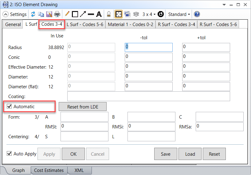
Other than the General tab, note that each surface in the Optical element (Left and Right surfaces in this case) will have two tabs each, allowing users to enter data corresponding to ISO 10110 drawing codes 3-4 and 5-6. “Codes 3-4” include Radius, Conic, Effective Diameter, Diameter, Diameter (flat), Coating, Form and Centering Errors. “Codes 5-6” include Imperfections, Laser Damage, Texture, Chamfer and other surface specifications.

Other surface and material characteristics are left for the user to fill in as appropriate.

If using the ISO Optical element Drawing with a Singlet or a Doublet, one extra “Material” tab for each Optical element will be present. This tab includes properties of the material: name of the Glass, Index of refraction, Abbe number, Thickness, Stress Birefringence, Bubbles, Inhomogeneity, and other material specifications.

References
- “ISO 10110 Optics and Optical Instruments – Preparation of drawings for optical Optical elements and systems: A User’s Guide”, by Ronald K. Kimmel and Robert E. Parks, eds.
- OpticStudio help files
- Reference Source: https://www.zemax.com/
