Why Intermediate Image Optimization Matters
In many optical systems, performance is not only defined at the final image plane.
Instead, a focal point, intermediate image, or spatial filter is intentionally placed between optical components. Common examples include:
- Keplerian telescopes
- Laser beam expanders
- Spatial filtering systems with pinholes
- Relay optics and afocal imaging systems
In these systems, optimization must be performed at an intermediate surface, not just at the final image plane. This article demonstrates how to design and optimize such a system using a telescope beam expander as an example.
Example System: Inverse Keplerian Beam Expander
We consider a laser beam expansion system that includes an intermediate focus with a pinhole filter, followed by collimation.
Design Inputs
- Wavelength: 532 nm
- Laser power: 50 mW
- Laser linewidth: 1–2 nm
- Input beam diameter: 1.2 mm
Output Requirements
- Pinhole spatial filter between lens groups
- Output beam diameter: 30 mm
- Total optical track: < 150 mm
This configuration corresponds to an inverse Keplerian telescope, commonly used for laser beam expansion and spatial filtering.
Keplerian vs Galilean Telescope Configurations
The Keplerian telescope, invented by Johannes Kepler in 1611, uses:
- A positive objective lens
- A positive eyepiece lens
Key characteristics:
- Lens separation = sum of focal lengths
- A real beam waist (focus) between lenses
- Enables spatial filtering
- Produces an inverted image
- Larger field of view and eye relief
By contrast:
Galilean Telescope
- One positive (focusing) lens
- One negative (defocusing) lens
- No real focus between lenses
- More compact
- No spatial filtering possible
For systems requiring a pinhole filter, the Keplerian configuration is mandatory.
Beam Expansion Principle
In a Keplerian beam expander:
- The beam waist occurs at the intermediate focal plane
- The beam diameter scaling is set by the focal length ratio:
Beam Expansion Ratio = f2/f1
For example:
- If the second lens focal length is 25× the first,
- A 1.2 mm input beam expands to 30 mm
Optimizing at an Intermediate Surface in OpticStudio
In Zemax OpticStudio, optimization is typically performed at the image surface. However, systems with intermediate images require a different approach.
The IMSF Operand (Image Surface Shift Function)
The IMSF operand allows you to:
-
Temporarily redefine which surface is treated as the image surface
-
Evaluate merit function operands at an intermediate focus
-
Optimize:
-
Spot size at the pinhole
-
Wavefront quality
-
Focus location
-
Important notes
- IMSF affects only a temporary copy of the lens data used by the Merit Function
- It does not modify the actual lens data
- Care is required if the selected surface is before the system stop
The design performance is shown below:


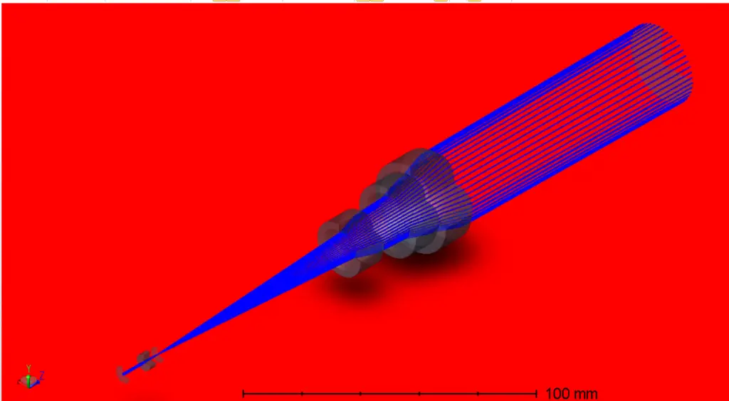
The intermediate focusing point is shown below:
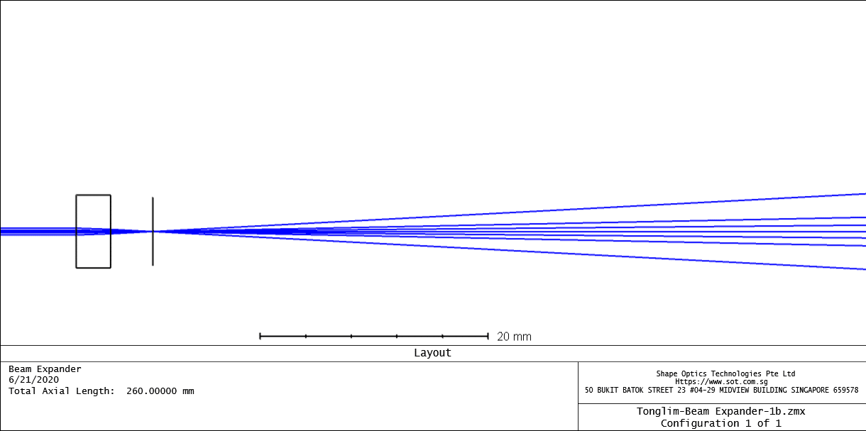
The focusing image performance is shown below:

The collimating performance with the beam diverging angle at 16 mrad.
