
Range-Doppler imaging leverages Doppler shift information to achieve spatial resolution beyond the classical diffraction limit. By jointly processing range and Doppler frequency, a two-dimensional image can be reconstructed even when using a single detector. This technique has been widely adopted in radar systems, where the relatively large beamwidth naturally produces a wide Doppler spread, enabling enhanced cross-range resolution.
In comparison, LiDAR systems operate with significantly narrower beamwidths and diffraction-limited spot sizes. While this provides superior range resolution, it restricts the field of view (FOV) and limits cross-range resolution when using conventional detector configurations. To form a Range-Doppler image spanning more than a single pixel, a broader illuminated area and a Detector Array System (DAS) are required.
When the DAS angular sampling is matched to the diffraction limit, Doppler imaging can extract elevation and cross-range information beyond the diffraction constraint. This capability enables resolution performance superior to traditional detector-array imaging alone, particularly in long-range observation scenarios, such as airborne or spaceborne platforms.
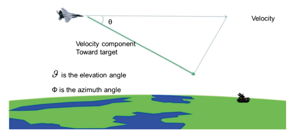
Microwave radar systems can generate 2D imagery with a single detector due to their wide beams, whereas LiDAR compensates for its narrower FOV through Doppler-based angular discrimination. When a LiDAR platform moves toward a target at constant velocity, the radial velocity component varies with elevation angle (ϑ) and azimuth angle (φ). This angular dependence produces distinct Doppler shifts across the scene, allowing the system to separate spatial features and achieve improved cross-range resolution.
In summary, although Range-Doppler imaging in LiDAR is more challenging than in radar due to its narrow beamwidth, it provides exceptional long-range imaging and elevation sensitivity. When combined with optimized detector arrays and motion-induced Doppler diversity, LiDAR systems can surpass conventional diffraction-limited performance, making them well suited for aerial surveillance, remote monitoring, and precision sensing applications.
Doppler Shift and Velocity Relationship
| Velocity (µm/s) | Doppler Frequency (Hz) |
|---|---|
| 1 | 1.29 |
| 10 | 12.9 |
| 100 | 129.03 |
| 1000 | 1290.32 |
Doppler Frequencies from Surface Vibration
| Vibration Freq. (Hz) | Amplitude (µm) | Max Velocity (µm/s) | Max Doppler (Hz) | Sample Time (ms) |
|---|---|---|---|---|
| 10 | 1.0 | 63 | 81 | 24.7 |
| 50 | 1.0 | 314 | 405 | 4.9 |
| 100 | 1.0 | 628 | 810 | 2.5 |
| 200 | 1.0 | 1257 | 1622 | 1.2 |
| 10 | 0.1 | 6 | 8 | 250.0 |
| 50 | 0.1 | 31 | 40 | 50.0 |
| 100 | 0.1 | 63 | 81 | 24.7 |
| 200 | 0.1 | 126 | 163 | 12.3 |
Cross-Range Resolution Explained
Cross-range resolution describes a system’s ability to distinguish between objects located at the same distance from the sensor but separated laterally—perpendicular to the line of sight.
Key Characteristics
- Orthogonal Resolution: Measures spatial separation across the imaging plane, not along the range direction.
- Beamwidth & Wavelength Dependence: Narrower beamwidths, larger apertures, and shorter wavelengths yield finer cross-range resolution.
- Doppler-Based Enhancement: Motion-induced Doppler variations enable angular discrimination beyond static diffraction limits.
- Practical Applications: Essential in SAR imaging, airborne LiDAR mapping, vibration sensing, and object discrimination in autonomous systems.
In essence, cross-range resolution determines how finely a sensing system can resolve side-by-side features, and Doppler-based techniques provide a powerful method for enhancing this capability beyond conventional optical constraints.