Non-Sequential optical design enables rays to propagate through optical systems without a predefined surface order. Unlike sequential ray tracing, rays in Non-Sequential Mode can reflect, refract, scatter, diffract, split, and even return to objects they have previously encountered.
This capability makes Non-Sequential Mode essential for analyzing illumination systems, stray light, scattering, diffraction, coherence effects, and absorption, as well as for modeling complex opto-mechanical geometries. A Mixed Mode workflow combines the strengths of sequential imaging design with non-sequential physical realism.
What Is Non-Sequential Ray Tracing?
In Non-Sequential Mode, rays—referred to as NSC rays—are not constrained to a fixed order of surfaces. Instead, they interact dynamically with any object they encounter.
Key characteristics include:
- Ray splitting into reflected, transmitted, and diffracted components
- Surface and bulk scattering
- Diffraction at phase surfaces or diffractive objects
- Multiple interactions with the same object
NSC analysis supports:
- Radiometric data collection on detectors
- Ray database storage for post-processing
- Detectors modeled as planar, curved, or 3D volume objects
Polygon Object Modeling
Polygon Objects (POBs) allow efficient modeling of faceted optics, prisms, and freeform structures. These objects can also be imported directly from CAD tools using STL files, making NSC ideal for realistic opto-mechanical integration.
Applications include:
- Light pipes and guides
- Micro-prism films (e.g., BEF)
- Faceted reflectors and baffles


Source Modeling in Non-Sequential Mode
Non-Sequential Mode provides a wide range of physically meaningful source models.
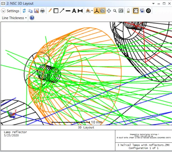
In one example, zooming into the NSC 3D Layout reveals the helical filament structure of lamps modeled using the Source Filament object. This allows accurate representation of:
- Filament geometry
- Near-field emission behavior
- Self-shadowing and internal reflections
Complex Geometry Creation
NSC supports:
- Boolean solids
- Imported CAD assemblies
- Nested and overlapping objects
This makes it possible to build manufacturable optical systems, including housings, reflectors, lenses, and mechanical features—something not feasible in purely sequential workflows.


Ray Splitting and Scattering
NSC ray tracing naturally supports partial reflection and transmission at every surface.
For example, a Brightness Enhancement Film (BEF) can be modeled using a Polygon Object (POB). When Simple Splitting is enabled, performance can be improved dramatically—approximately 6× faster than full splitting in many illumination scenarios—while maintaining sufficient accuracy.

Diffraction Grating Modeling
While diffractive optical elements can be modeled in both Sequential and Non-Sequential Modes, NSC provides a major advantage through ray splitting into multiple diffraction orders.
In this diffraction grating example:
- Rays are diffracted into orders −2 through +2
- Diffraction occurs in both reflection and transmission
- Power distribution among orders can be directly analyzed
This is particularly useful for spectroscopy, beam shaping, and wavelength-selective optics.

Coherence Modeling
Non-Sequential Mode supports coherent ray tracing, enabling simulation of interference and coherence effects.
In a two-source example:
- A small angular tilt between sources produces interference fringes
- As propagation distance increases toward the coherence length, fringes gradually wash out
This capability is critical for:
- Laser interference analysis
- Speckle studies
- Coherent illumination systems

Absorption and Energy Deposition Analysis
NSC enables true volumetric absorption analysis using Detector Volume objects.
In a laser flash-pump cavity example:
- Source Tubes represent flash lamps
- Toroidal mirrors form the cavity
- A Cylinder Volume simulates the laser crystal
- A Detector Volume overlapping the crystal records absorbed energy
This allows visualization and quantification of:
- Pump efficiency
- Spatial absorption distribution
- Thermal loading regions


Why Use Mixed Mode?
Mixed Mode workflows combine:
- Sequential Mode for precise imaging optimization
- Non-Sequential Mode for physical realism, stray light, scattering, and absorption
This approach is ideal for systems that require both high imaging performance and accurate illumination or stray-light behavior, such as cameras, sensors, LiDAR, and projection optics.
Conclusion
Non-Sequential optical design expands the scope of optical simulation far beyond traditional imaging analysis. By enabling ray splitting, scattering, diffraction, coherence, and absorption modeling—while supporting real-world geometry—it provides unmatched insight into complex optical systems. When combined with Sequential Mode in a Mixed Mode workflow, it forms a powerful and complete optical design methodology.