The ISO Optical Element Drawing Tool in OpticStudio helps users create detailed optical element drawings that comply with ISO 10110 standards. This tool is particularly useful for creating precise representations of optical components, such as singlet lenses and doublets. In this article, we will demonstrate the use of the tool with a simple singlet lens as an example.

Step-by-Step Guide to Using the ISO Optical Element Drawing Tool
To begin, expand the tool settings and navigate to the General tab. In this tab, select the first surface of the optical element to be drawn. For this example, we will focus on a singlet lens with the component at the second surface.

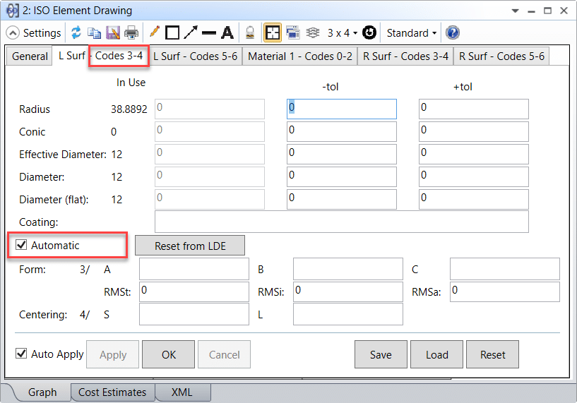
For each surface in the optical element (e.g., the left and right surfaces in the singlet lens), there will be two tabs corresponding to the ISO 10110 drawing codes:
- Codes 3-4: These codes include Radius, Conic, Effective Diameter, Diameter, Flat Diameter, Coating, Form, and Centering Errors.
- Codes 5-6: These codes cover Imperfections, Laser Damage, Texture, Chamfer, and other surface specifications.
Other surface and material characteristics are to be filled in as appropriate.

If using the ISO Optical Element Drawing tool with a singlet or doublet, an additional “Material” tab will appear. This tab contains material properties for the optical element, including:
- Glass Name
- Index of Refraction
- Abbe Number
- Thickness
- Stress Birefringence
- Bubbles
- Inhomogeneity
- Other material specifications
These properties help define the optical characteristics and performance of the element.

Additional Features and Considerations
The ISO Optical Element Drawing Tool in OpticStudio allows users to customize surface and material properties in line with the ISO 10110 standard. By completing the various tabs for each surface, optical engineers can create accurate drawings that reflect both the geometry and optical characteristics of their designs.
Conclusion
The ISO Optical Element Drawing Tool in OpticStudio simplifies the process of creating detailed and standardized optical element drawings. By understanding the different tabs and settings for surface characteristics and material properties, optical engineers can ensure their designs adhere to ISO 10110 standards for accurate, high-quality optical systems.
Reference
- “ISO 10110 Optics and Optical Instruments – Preparation of drawings for optical Optical elements and systems: A User’s Guide”, by Ronald K. Kimmel and Robert E. Parks, eds.