
Bio-fluorescence describes the physical process in which light is absorbed by a material and re-emitted at a different, usually longer, wavelength. This phenomenon is widely used in biomedical imaging, sensing, and life-science optics, and can be effectively modeled using optical design software.
Below, we outline a simple and practical approach to modeling bio-fluorescent material scattering, using a volumetric scattering object and wavelength-shift behavior.
System Overview
The example setup (attached at the end of this article) demonstrates the modeling of a bio-fluorescent object using a simplified optical system:
- A Source Ellipse launches a collimated beam of rays.
- Rays propagate toward Object 2, a volumetric object where bulk material scattering can occur.
- During bulk scattering, rays undergo a wavelength shift from an excitation wavelength (λ₁) to an emission wavelength (λ₂).
This configuration allows clear visualization of both scattering behavior and fluorescence-induced wavelength conversion.

Bulk Material Scattering with Wavelength Shift
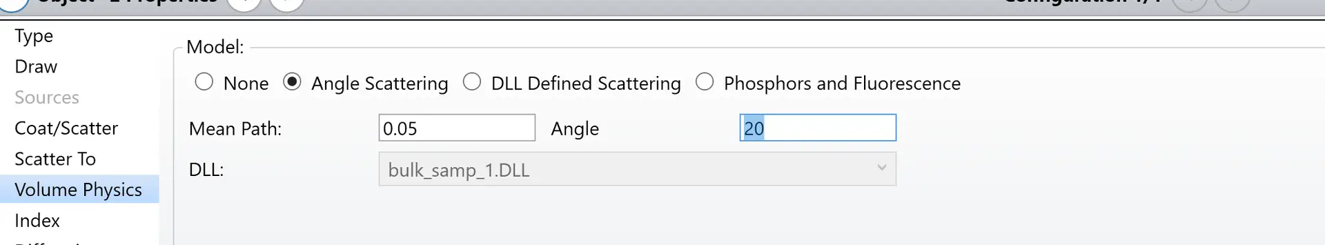
Within Object 2, bulk scattering is defined under the Bulk Material Scattering properties:
- Scattering model: Angle scattering distribution
- Mean free path: 0.05 mm
- Maximum scattering angle: 20°
In this example:
- All rays start at wavelength #1 (0.780 µm)
- Any ray that undergoes bulk scattering is shifted to wavelength #2 (0.900 µm)
- The wavelength-shift probability is set to 100%, meaning every scattered ray fluoresces
In general applications, wavelength-shift behavior is not limited to a single transition, and only a fraction of scattered rays may undergo fluorescence, depending on material properties.
Visualizing Fluorescence with Layout Filters
To verify the wavelength-shift behavior, a layout plot filter is used:
This filter displays only rays that have shifted from wavelength #1 to wavelength #2, allowing clear separation between excitation and emission paths.
Wavelength Separation Using a Beamsplitter
A second rectangular volume object is introduced to validate correct wavelength behavior. Its front face is coated with a wavelength-dependent beamsplitter coating:
TABLE SBICBEAMSPLIT
ANGL 45.0
WAVE 0.78 1.0 1.0 0.0 0.0 0.0 0.0 0.0 0.0
WAVE 0.90 0.0 0.0 1.0 1.0 0.0 0.0 0.0 0.0
According to this coating definition:
- Rays at 0.780 µm are fully reflected
- Rays at 0.900 µm are fully transmitted
Results and Interpretation

From the layout plot, the behavior is clearly observed:
- Non-scattered rays (no fluorescence) are reflected by the beamsplitter
- Scattered, wavelength-shifted rays (fluorescence emission) are transmitted
This confirms that:
- The bulk scattering model is functioning correctly
- The wavelength-shift tool accurately simulates bio-fluorescence behavior
Practical Applications
This modeling approach is useful for:
- Fluorescence microscopy system design
- Biomedical imaging simulations
- Optical sensor development
- Life-science and diagnostic optics
It provides a controlled and visual method to study how scattering, absorption, and wavelength conversion interact in volumetric materials.
Reference Sources
- Laikin, Milton. Lens Design. CRC Press, 2007
- Zemax Optical Design Program – User’s Guide
- Wikipedia – Optical scattering and fluorescence
- The design file used in this article is attached. Please download it to explore or modify the bio-fluorescence model. How to design Bio-fluorescence material scattering