Aspherization is one of the most powerful techniques in optical design for improving image quality. A well-placed aspheric surface can significantly reduce aberrations such as spherical aberration, coma, and astigmatism—often with fewer elements, lower weight, and improved manufacturability.
However, not every surface benefits equally from being made aspheric. Randomly adding aspheres can:
- Increase design complexity
- Slow optimization
- Raise manufacturing cost with little performance gain
This article introduces a fast and systematic method in Code-V OpticStudio to identify which surfaces in a design are the best candidates for aspherization.
Example System: Cooke Triplet Derivative
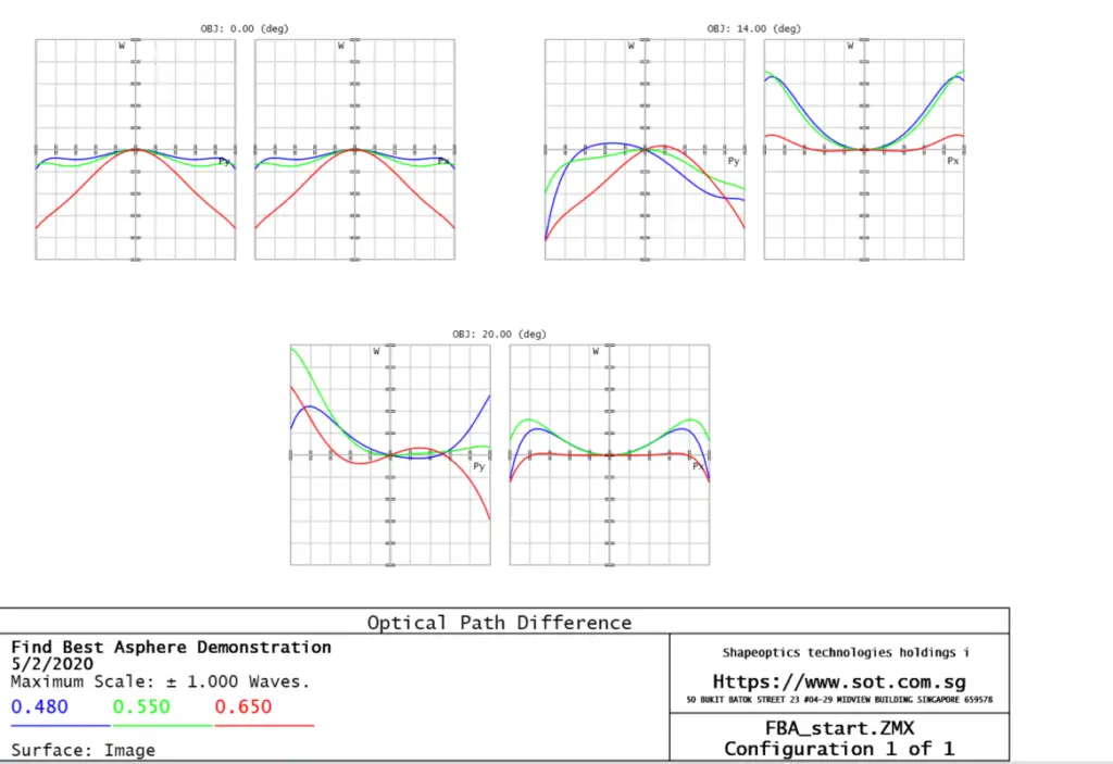
The example design is a Cooke triplet derivative, optimized for minimum RMS wavefront error.
Key characteristics:
- All radii and thicknesses are variable
- The last surface radius is constrained by an F/# solve
- System speed is maintained at f/5 throughout optimization
This type of system is ideal for demonstrating asphere selection because:
- It is well understood
- Aberrations are distributed across multiple surfaces
- Only a subset of surfaces will provide strong aspheric leverage


The Asphere Candidate Identification Tool
OpticStudio provides a tool that rapidly evaluates which surfaces will benefit most from aspherization.
What the Tool Does
The tool:
- Analyzes a range of surfaces
- Tests each surface’s potential performance improvement if converted to an asphere
- Ranks surfaces based on effectiveness
You can specify:
- Start surface
- Stop surface
- Maximum polynomial order (e.g., even aspheric terms)
This allows quick exploration without manually converting and testing each surface.
Criteria for Asphere Candidate Selection
For a surface to be considered a valid asphere candidate, it must meet all of the following conditions:
✔ Surface type must be Standard
✔ No conic constant already applied
✔ Surface must lie between air and glass
✔ Cemented surfaces are excluded (usually poor asphere choices)
✔ Curvature must be:
- A variable, or
- Controlled by a Marginal Ray Angle solve, or
- Controlled by an F/# solve
Surfaces that do not meet these criteria are automatically ignored by the tool.
Why These Conditions Matter
Air–Glass Interfaces
Aspheric surfaces are most effective at:
- Strong refractive boundaries
- Locations with significant ray height variation
Cemented surfaces typically:
- Have reduced refractive power
- Offer limited aberration correction leverage
Variable or Solved Curvature
If the surface curvature cannot change:
- The optimizer cannot fully exploit aspheric terms
- Performance improvement will be limited
Practical Workflow for Aspherization
A recommended workflow is:
- Optimize the all-spherical design first
- Run the asphere candidate identification tool
- Select the top-ranked surface
- Convert only that surface to an asphere
- Re-optimize
- Repeat if additional improvement is required
This approach:
- Minimizes design risk
- Keeps manufacturability under control
- Achieves maximum benefit with minimal complexity
Benefits of This Approach
- Rapid identification of high-impact surfaces
- Avoids unnecessary aspheres
- Faster optimization convergence
- Lower fabrication cost
- Cleaner, more robust designs
In many systems, one well-chosen asphere can outperform multiple poorly chosen ones.
Key Takeaways
- Not all surfaces benefit equally from aspherization
- Air–glass, high-power surfaces are usually best
- Cemented interfaces are poor asphere candidates
- Use analytical tools before adding aspheres
- Start spherical, then add aspheres strategically
Aspherization is most effective when it is deliberate and data-driven, not trial-and-error.