
Flash LiDAR and Scanning LiDAR differ fundamentally in how they illuminate a scene and acquire spatial information. These differences directly affect system complexity, resolution, eye safety, and application suitability.
Flash LiDAR Illumination
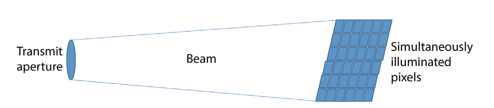
Flash LiDAR illuminates an entire scene simultaneously using a wide-angle laser pulse and captures the reflected signal with a 2D detector array.
Key Characteristics
- The illuminated area matches the field of view (FOV) of the detector array
- A large-divergence beam is required to cover all pixels at once
- A single laser pulse produces a full depth image
- Enables very fast image acquisition with no mechanical scanning
Because the laser energy is spread over a wide angular region, the instantaneous power density per pixel is lower, but the total emitted energy per pulse is typically higher than in scanning systems.
This architecture is well suited for:
- Short- to medium-range imaging
- High-speed scene capture
- Situations where motion artifacts must be minimized
However, longer eye exposure duration and higher total pulse energy require careful compliance with Maximum Permissible Exposure (MPE) limits.
Scanning LiDAR Illumination
Scanning LiDAR uses a narrow laser beam that is steered across the scene sequentially, either mechanically or electronically.
Key Characteristics
- Small beam divergence
- High irradiance at the illuminated spot
- Scene is built pixel-by-pixel over time
- Lower instantaneous exposure per point on the eye
Scanning LiDAR systems typically achieve:
- Longer operating range
- Higher angular resolution
- Better eye safety margins due to short dwell time
This architecture is widely used in:
- Automotive LiDAR
- Airborne and topographic mapping
- Long-range surveillance and sensing
Diffraction Limit and Beam Divergence
The minimum achievable angular width of a LiDAR beam is constrained by the diffraction limit, given by:
θ ≈ λ/D
where:
- D is the diameter of the transmit aperture
- λ is the laser wavelength
This relationship shows that:
- Larger apertures produce narrower beams
- Longer wavelengths increase beam divergence
Scanning LiDAR benefits more directly from large apertures, while Flash LiDAR intentionally expands the beam well beyond the diffraction limit to illuminate a wide area.
Gaussian vs Super-Gaussian (Flat-Top) Beams
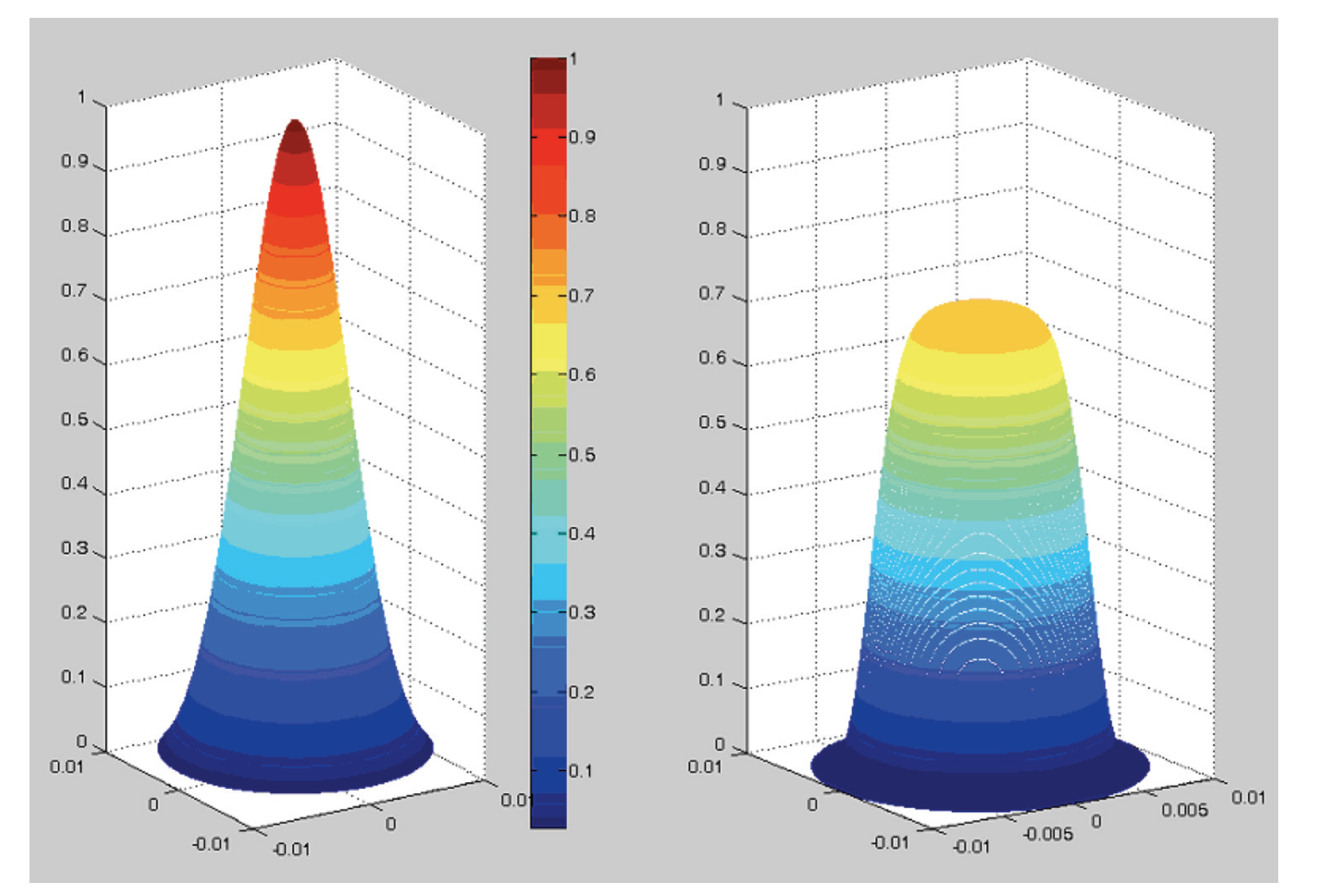
LiDAR transmit beams are commonly Gaussian, but super-Gaussian (flat-top) profiles are sometimes preferred, especially in Flash LiDAR.
Gaussian Beam
- Energy concentrated at the center of the beam
- Smooth intensity roll-off
- Efficient generation and propagation
- Results in non-uniform illumination across the detector array
Super-Gaussian / Flat-Top Beam
- More uniform intensity distribution
- Reduced peak intensity
- Less clipping at the aperture edges
- Improved pixel-to-pixel uniformity in Flash LiDAR
For a generalized super-Gaussian beam, the intensity profile can be expressed as:
I(r) = a⋅exp[−{(r−b)/c}^N]
where:
- a is the peak amplitude
- b is the beam offset
- c defines the beam width
- N is the beam order (higher N → flatter top)
Imaging Implications
Flash LiDAR
- Captures full scenes in a single pulse
- Ideal for high-speed imaging
- Requires higher total pulse energy and careful eye-safety design
Scanning LiDAR
- Builds images sequentially
- Offers superior range and angular resolution
- Easier to maintain eye safety at high power
The choice between Flash and Scanning LiDAR depends on range requirements, frame rate, eye safety constraints, and system complexity.
Summary
Flash LiDAR and Scanning LiDAR represent two distinct illumination strategies. Flash LiDAR trades beam concentration for instantaneous wide-area coverage, while Scanning LiDAR concentrates energy into a narrow beam for higher resolution and longer range. Beam shaping—Gaussian versus super-Gaussian—plays a critical role in optimizing illumination efficiency and image uniformity, particularly in Flash LiDAR systems.
Understanding these differences is essential for selecting the right LiDAR architecture for a given application.